Getting Light into a Monochromator
In this tutorial we give a brief introduction to getting light into a monochromator, and how much you can expect to get out. While the emphasis is on coupling Oriel Light Sources to Oriel Monochromators, the same general principles apply to collecting light from any source for analysis. Specifically, all of the collection principles we will cover here may be applied to spectrographs as well as monochromators. Throughout these pages, we use the term monochromator for both instruments.
Geometrical extent is discussed on see Light Collection and Systems Throughput. Here it is defined as G = AΩ, where A is the image area at an image plane in the system and Ω is the associated solid angle. We also note that the lowest geometrical extent of any component in an optical system limits system throughput. In many spectroscopic systems, the monochromator is the component with lowest geometrical extent. The geometrical extent of the monochromator is the product of the slit area and the solid angle of acceptance. Our 77200 and 77700 1/4 m Monochromators have larger geometrical extent than our smaller 1/8 m monochromators and spectrographs.
Once you have chosen your monochromator you can do nothing to increase it’s geometrical extent, so you must think about source and detector coupling. Here we offer some help to make sure that the input optics, which you can optimize, do not limit the system throughput.
If you are using a monochromator in conjunction with your source to provide a monochromatic excitation beam, stray light is usually a small concern; it is often the goal to get as much light into the system as possible, regardless of geometry. However, if you have a detector at the output, particularly a large area detector such as Oriel’s InstaSpec™ CCD, stray light may be an important consideration. You may improve the signal to noise ratio of your system by limiting the geometrical extent at the input to the monochromator. Our 77400 and 77700 models have internal baffles to do this.
Acceptance Cone and Monochromator Optics
Figure 1 shows the optics of our 77200 1/4 m Monochromator. Our 77250 1/8 m, 77700 MS257™, and Cornerstone™ Instruments have similar layouts.
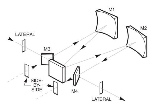
Figure 2 shows the optical equivalent of the input to the monochromator in Figure 1.
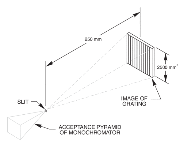
It is easy to see from Figure 1 and Figure 2, that the monochromator has an acceptance pyramid, often described by an F/#. The position and dimensions of the internal optics determines the pyramid. The optical equivalent is a grating image located behind the slit as shown in Figure 2. Only light that passes through the slit in the direction of this grating image is useful.
Usually the pyramid is treated as an acceptance cone with the cone peak on the center of the slit, and the F/# defined by an equivalent circle on the square grating image. The “equivalent circle” is the circle that has the same area as its corresponding square; this definition results in a more accurate F/# approximation than using either the inscribed or exscribed circle. Based on the equivalent, the 77200
1/4 m has an acceptance cone with half angle of 6.4°. The half angle for the 77250 1/8 m is 7.7° and the MS257™ is 7.4°. The Cornerstone 130 and 260 Monochromators have an acceptance cone with half angle of 7.7° and 7.4° as well.
Table 1 Half Angle and Solid Angle Values for Various F/# Instruments
| F/# | θ1/2 (degrees) | Ω (steradians) |
|---|---|---|
| 2.0 | 14.48 | 0.200 |
| 2.2 | 13.14 | 0.164 |
| 2.4 | 12.02 | 0.138 |
| 2.6 | 11.09 | 0.117 |
| 2.8 | 10.29 | 0.101 |
| 3.0 | 9.59 | 0.088 |
| 3.2 | 8.99 | 0.077 |
| 3.4 | 8.46 | 0.068 |
| 3.6 | 7.98 | 0.061 |
| 3.8 | 7.56 | 0.055 |
| 4.0 | 7.18 | 0.049 |
| 4.2 | 6.84 | 0.045 |
| 4.4 | 6.52 | 0.041 |
| 4.6 | 6.24 | 0.037 |
| 4.8 | 5.98 | 0.034 |
| 5.0 | 5.74 | 0.031 |
Relevance of Monochromator F/Number
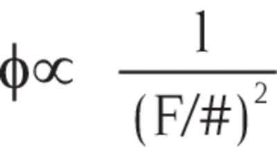
In Light Collection and Systems Throughput we discussed the F/number concept. Lower F/#s are usually associated with higher light gathering power or throughput. This comes from the concept that light collected, or flux Φ, is inversely proportional to the square of the F/#. That is:
Geometrical extent, as mentioned earlier, was shown to be more fundamental than F/#. Our 77250 and 77200 Monochromators provide a good example of how geometrical extent is a better measure of throughput than F/#. The 77250 has an effective F/# of 3.7, and the 77200, F/4.4. Based on the relationship between F/# and collected light, you would expect that the 77250 would have the higher throughput by (4.43/3.72)2 = 1.42 times. However, to maintain a given bandwidth, the slits of the 77200 are twice as wide as those of the 77250. Ignoring the slit height difference, the result using geometrical extent equations is that for a broadband source, the throughput of the 77200 is 1.38 times that of the 77250.
F/# is only the sole criterion when comparing monochromators of equivalent slit area.
Entrance Slit is Imaged on the Exit Slit
Light that strikes the grating is dispersed so that each wavelength leaves the grating at its appropriate angle (see Grating Physics for the theoretical discussion). A small range of wavelengths leave the grating at the correct angle to pass through the exit slit.
We can ignore the wavelength dispersion effects in order to appreciate an important result of the monochromator optical system; the optics image the entrance slit onto the exit slit (onto a detector in a spectrograph). For low grating angles the imaging is often effectively 1:1, however this varies from instrument to instrument. MS257™ has 110% magnification through the system. This has great significance. The size and location of the emergent beam is vital when trying to get the monochromator output onto a small detector, or into a fiber optic at the exit slit. The size and location of the output is largely determined by the illumination of the input slit.
Optimizing a Given Monochromator
You must choose the most efficient grating and optimize the slit size of any monochromator for the highest throughput.
Diffraction Grating
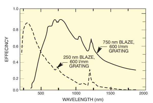
Choose the most efficient grating for the wavelength of interest. The grating blaze wavelength is a good guide. When working with a broad spectral range choose a grating that compensates for other system inefficiencies. Figure 3 shows the relative efficiency of two of our gratings. The grating blazed at 750 nm is obviously better above 500 nm, while the 250 nm blaze grating is superior in the ultraviolet.
Slit Width
The slit width is usually selected to achieve the bandpass or spectral resolution required. To optimize throughput, always use the widest slits you can, while maintaining your other system requirements.
The effect of increasing the slit width depends on:
- the source image in the slit plane
- the source spectrum
If the source image on the input slit is large and uniform, then doubling the width of both slits gives about four times as much radiation into the monochromator for a broadband source with a flat spectral distribution. Strong spectral features can radically change this “gain”.
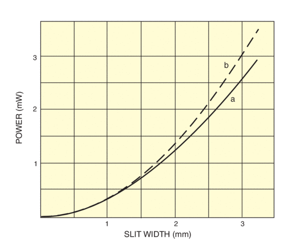
Figure 4 shows the measured variation of power through the 77250 1/8 m Monochromator against slit width, at 500 nm, for the 6333 100 W QTH lamp. An F/1.5 condenser was used to collect the light and the beam was focused on the monochromator at F/4.5, so the source image on the slit measured 6.9 by 12.6 mm, overfilling the widest slit.
Doubling the width of both slits gives twice as much power for a monochromatic source, which overfills the slit width.
Many sources produce non uniform and irregular images on the input slit, and have spectral line structure. Doubling the width of both slits produces a power increase between 2 and 4.
If the slit is bigger than the source image on the slit, then opening the entrance slit has no effect on the power through the monochromator. In this case, doubling the width of the exit slit only increases the power by about 2 for a broadband source.
Slit Height
When the source image in the slit plane is long then use the longest slits you can. Long slits give more throughput for a long source image on the slit. With the light from the model 6269 kW xenon lamp collected at F/1 and imaged at F/5, the arc image on the slit is about 16 mm tall. The 18 mm fixed slits of the 77200 give 30% more power through the 77200 than 12 mm slits on the Multiple Slit Wheel.
We referred above to the imaging of the input slit on the output. The useful slit length may be smaller than the 12 or 18 mm quoted if the output is to fall on a small sample, detector or fiber optic. In these cases, you must take care to concentrate the input flux on the area of the entrance slit that matches the useful zone of the exit slit. Longer slits do not necessarily give an advantage, and can add stray light to the system.
Summary
- Choose the most efficient grating
- Use the widest slits you can
- Use the longest slits practical
- Illuminate the input slit for most radiation in the useful zone of the output slit
Ensure that the long dimension of the source matches the long dimension of the slit. You may need to turn the monochromator on its side to achieve this.
Radiating Element Size
The size of the primary radiating element is crucial to the choice of input optics. Element sizes may be found on see DC Arc Lamps for arc lamps and see Quartz Tungsten Halogen Lamps for QTH lamps. We deal summarily with the two extreme cases and at some length on the typical intermediate case.
Case I - Large Radiating Area
A large uniformly emitting source may fill the base of the acceptance cone. (Figure 2). Input optics will not increase the radiation through the monochromator, nor will moving the monochromator towards or away from the radiating area, providing the area continues to fill the base of the cone. To get most radiation through, use the largest slits you can. With a broadband source and a given bandwidth, the throughput of the 77200 1/4 m Monochromator can be 4.2 times that of the 77250 if you use the 18 mm long slits on the 77200.
Case II - “Point Source” (or Lasers)
The theoretical point source does not exist, but some very small fiber optic sources, pinhole images and laser sources (or laser induced radiation) may approximate a point source of radiation. For the point source approximation, any magnified image of the radiating source should underfill the slit width.
With point sources, all you need to do is collect as much light as possible for the source using low F/# optics, and focus it on the slit opening at an F/number, which is equal to the monochromator F/number.
Example
If you collect at F/2 from a 6 µm diameter single mode fiber and reimage on the slit at F/10, you might magnify by 5; the result (ignoring diffraction and lens aberrations) is about 30 µm image on the slit. If the slit width is 1.56 mm (5 nm bandpass with the 77700 and a 1200 l/mm grating), then the point source approximation is valid. Focusing at F/4 doesn’t increase the radiation through the monochromator, but it may give slightly better resolution since the input spot is smaller.
Special Considerations for High Power Beams
Caveats
1. Any actual image size may be much larger than expected from a simple calculation because of optical aberrations and diffraction effects.
2. If you don't fill the input slit, the bandpass is not determined by the dispersion and slit sizes, but by a convolution of the input spot size and the output slit width.
3. Operating at high F/number leads to underfilling of the grating and improved resolution, but in extreme cases, loss of resolution (see Grating Physics).
4. Operating at high F/number with high power laser sources can lead to grating damage.
Case III - Radiating Element and Slit of Comparable Dimensions
The source of radiation and slit size often have comparable dimensions. Our intense arc sources have dimensions from 0.25 x 0.25 mm, to 3.0 x 2.6 mm. The compact high brightness tungsten halogen filaments (see Quartz Tungsten Halogen Lamps) have dimensions from 1.7 x 0.65 to 6 x 16 mm. The slit dimensions for a 10 nm bandpass (with a 1200 l/mm grating) on the 77250 1/8 m Monochromator are 1.56 x 12 mm.
Fluorescing regions caused by focused beams from incoherent (i.e. non-laser) radiation also have mm dimensions.
We start by assuming that the monochromator, grating and slits are all optimized as previously suggested. We list two rules, comment extensively on them and then give two examples.
The two rules for most efficient coupling:
1. Always fill the monochromator acceptance cone.
2. Get as much light as possible through the slit while observing Rule 1.
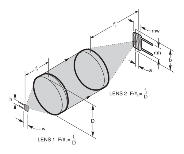
The problem is that the two rules are interlinked and can be satisfied by many optical systems. Most of our discussion deals with a two optic system; a condenser lens collecting and collimating light from the radiation source, and a focusing lens. Two lens systems, such as the one in Figure 5, simplify the design implementation because you can set the length of the collimated arm to suit your set up.
A single lens system is no better at satisfying our two rules, and you have the added complication of the relationships between:
- source-lens distance and light collection
- source-lens and lens-slit distances and source magnification
- lens-slit distance and focusing F/#
You also need to use a large diameter optic for efficient collection from the source. Our Monochromator Illuminators exemplify efficient implementation of a single optic solution.
Photomax™
PhotoMax™ Lamp Housing is designed for Rules 1 and 2. The ellipsoidal reflectors collect light very efficiently and focus it on the slit. If you use a low power arc lamp or other small volume radiating element, you will get more light into a monochromator using the appropriate PhotoMax™ than with any condenser system. (Note: it is crucial that the radiating system be small, ie. arc lamps with gaps less than approximately 1.5 mm.) Because selection of optics are not required, we will not discuss the PhotoMax™ systems in detail.
Rule 1
Filling the acceptance cone means focusing the beam on the slit at the correct F/number, ie. F/4 for the 77250, 77400 and 77700 or F/4.4 for the 77200. Focusing at these F/#s results in an overfill of the grating along vertical and horizontal diameters and underfill of the corners. If you focus at lower F/#, light is lost as it misses the grating and reflects inside the monochromator as stray light. All the light strikes the grating if you focus at a higher F/#, but the image of the radiating element on the slit is larger than it needs to be, with system efficiency loss.
Remember that the F/# quoted for monochromator input is the lens focal length divided by the beam diameter. This F/# is greater than the lens F/# since the beam usually does not completely fill the full lens aperture.
Rule 2
Figure 5 shows a typical optical system. Light from a filament is collected by Lens 1, and focused on the monochromator slit by Lens 2. The magnification, m, of the filament on the slit is given by the ratio of the F/numbers.
m = (F2/#)/(F1/#)
Because the beam is “collimated”, the beam diameter is approximately constant, so the magnification is also given by the ratio of the focal lengths, f2/f1.
Our condenser sources produce beams with diameters of 33 mm, 48 mm and 69 mm. Larger beam diameters require bulky and more expensive lenses. We use the 33 mm beams for lamps rated to 500 W and the 48 mm beams for lamps from 500 W - 1kW. Our Aspherabs® produce a 69 mm low aberration beam from any lamp.
Defining the beam diameter lets you fix Lens 2. For a 33 mm beam and the F/4.5 required for the 77200 Monochromator, Lens 2 should have a clear aperture of at least 33 mm and a focal length of 33 x 4.4 = 145.2 mm. Of the simple lens forms, plano-convex lenses give least aberration, so any 1.5 or 2 inch diameter plano-convex lens with 150 mm focal length can serve as Lens 2.
Condenser Lens
A simple model based on Figure 5 is very useful in showing the importance of choosing a low F/# lens for Lens 1 and in illustrating proper orientation of the source.
We assume a uniform rectangular radiating element of dimensions “w x h”. Lens 2 is fixed. To allow for magnification, the F/# of Lens 1 must be (F/#2)/m, where “m” is the magnification of the radiating element to the slit.
The effective slit dimensions are “a x b”. These values are determined by such constraints as bandpass and detector size.
The magnified image of the source at the slit plane has dimensions “mw x mh”. Usually this image is larger than the slit dimensions so there is a vignetting loss. The vignetting loss depends upon the source shape, slit shape, and magnification; we will simply use the parameter V to quantify this effect. V is equal to 1 when the source image is smaller than the slit, indicating no loss. However, when the source image completely overfills the slit, V is the ratio of slit area to magnified source area.
V = (a x b)/(mw x mh)
The power which enters the slit is proportional to
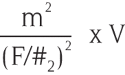
The first term reflects how light collection is proportional to 1/(F/#1)2. The second term is the vignetting loss.
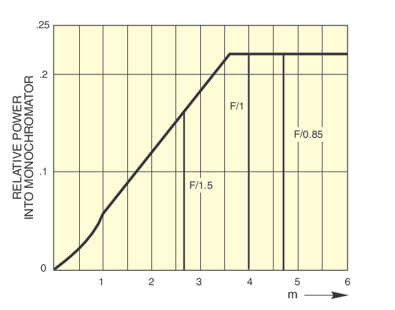
Fig 6. shows a typical graph of relative power through the slit vs. magnification. There are three regions. At very low magnification, V = 1, but very little power is collected. Power collected increases as m2, and power into the monochromator obeys the same relationship.
At magnification m1, the width of the radiating element image reaches the slit width, and V starts to decrease as 1/m. In this region
V* = a/mw
Therefore, the power relationship above allows for collected radiation to increase as m.
At m2, the magnified source image fills the slit height. For m>m2, V follows its full definition on the previous page. This inverse relationship with m2 cancels the direct m2 increase in collected radiation so that power into the monochromator is constant, proportional to (a x b) / (w x h). (These are source and instrument parameters, not affected by choice of optics.)
* This expression for V follows from the earlier definition but in this case the useful height of the slit, b, is equal to mh. The two terms cancel and you are left with V = a/mw.
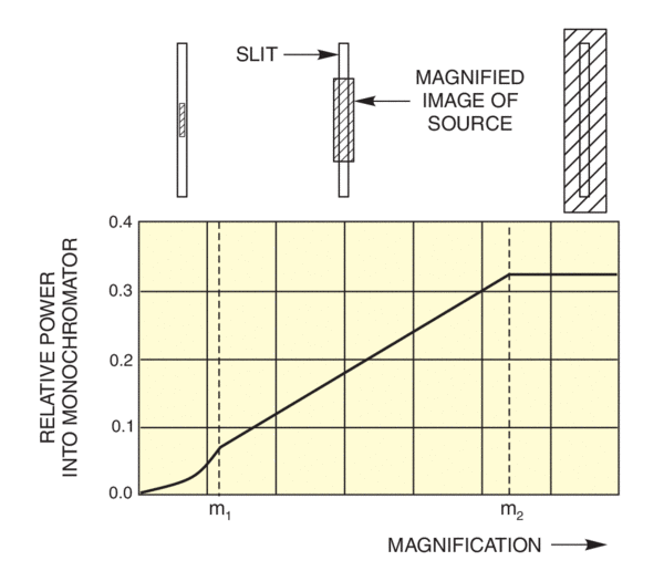
Figure 6 is helpful for selection of a condenser lens. It lets you know what F/# is needed to achieve the best possible performance.
F/#2 is already chosen to fill the monochromator acceptance cone. The condenser F/#, F/#1 is given by:
F/#1 = (F/#2)/m
Knowing F/#2, you can quickly mark in the available condensers on the magnification diagram. Figure 7 shows this diagram for the 6332 50 W QTH Lamp at F/4 into the monochromator.
Which Lamp?
The ideal radiation source for this lens collection and refocusing method is a high radiance element with the same shape as the slit. The size of the radiating element should be at least the slit dimensions divided by m. The largest practical value of this ratio for Oriel mirrors and condensers is 5.
Selection of a radiation source should be based on radiance at the wavelength of interest, and how much of the magnified image fits inside the useful slit area.
Example
Select the optics for a 2 nm bandwidth in the visible from the model 6253 150 W xenon lamp with the 77200 1/4 m Monochromator.
The most efficient grating is the model 77233 1200 l/mm grating with 350 nm blaze. The monochromator slit width for 2 nm bandpass is 0.63 mm. The closest fixed slit is 0.6 mm (a = 0.6). Assume a useful slit height of 12 mm (b = 12). The arc lamp is normally mounted vertically, so the arc is oriented properly for the normally vertical monochromator slit. The dimensions of the arc are 0.5 mm (w) by 2.2 mm (h).
An F/4.4 focusing lens is required to fulfill Rule 1.
Working with 1.5 Inch Series accessories means a beam diameter of 33 mm, so the focusing lens focal length should be ca. 150 mm.
In choosing the condenser, a diagram like Figure 6 of relative power through the slit against m, shows that the molded aspheric condenser with F/0.85 gives better results than the F/1. In fact, the F/0.85 lens gives close to maximum achievable performance.
So the optics should be:
Lens 1. The F/0.85 Condenser found in the 66919 Research Source.
Lens 2. A 150 mm focal length glass plano-convex secondary focusing lens. (model 40570)
Note that the Pyrex® F/0.85 condenser has poor transmission below 350 nm. Thus for the ultraviolet, the best combination is the F/1 condenser in the 66907 Source, with a 150 mm focal length fused silica plano-convex lens (model 41570), and a 1200 l/mm grating with 250 nm blaze.