Light Detection and Ranging (LiDAR)
LiDAR is an active remote sensing technique that is similar to RADAR but, instead of using radio waves as a radiation source, it uses laser pulses. In this technique, a laser source emits pulses that are directed towards the target of interest, such as a terrain landscape. The pulses encounter the terrain and a portion of the laser energy is reflected back to a sensor located near the source. By measuring the round-trip travel time of the emitted laser pulses, the LiDAR system can determine the distance between the sensor and the mapped terrain. LiDAR can generate a dense, three-dimensional (3D), geo-referenced point cloud, i.e., a set of data points in space, for the reflective terrain landscape when combined with a Global Positioning System (GPS) and an Inertial Measurement Unit (IMU). Compared to traditional photogrammetric approaches, LiDAR is less sensitive to the current weather, time of the year, or time of the day during which data is collected. Furthermore, this technique can generate high-resolution 3D topographic surface information more rapidly due to its ability to penetrate vegetation.
LiDAR has become an established method for generating dense and accurate elevation data across landscapes, shallow-water areas, and project sites. LiDAR systems are often placed in aircraft where data can be rapidly collected over large areas. LiDAR data is also collected from ground-based stationary and mobile platforms for street mapping and autonomous driving applications. These collection techniques are popular within the surveying and engineering communities since they can enable the accurate development of railroads, roadways, bridges, buildings, breakwaters, and other shoreline structures. This section mainly discusses airborne applications of LiDAR systems.
Principles of LiDAR Data Collection
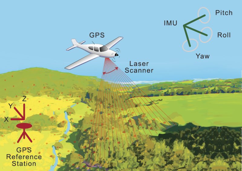
The basic principles of LiDAR are shown in Figure 1. The airborne LiDAR system is comprised of three major time-synchronized components: a laser scanner unit, a GPS, and an IMU. The laser scanner is composed of a laser range finder unit, which is based on time-of-flight distance measurement techniques, and a beam deflection device that creates the desired scanning pattern. The GPS provides the absolute position of the sensor platform (plat), and the IMU records the angular attitude of the platform (including roll, pitch, and yaw/heading). This enables the system to generate the aircraft's absolute position (X, Y, Z) at any given time. The position is synchronized using the detector's recording system for each recorded reflection. The required recording speeds and the amount of collected data require strong, real-time computation capabilities on board the aircraft.
Most commercial airborne sensors are based on the LiDAR principle of pulse round-trip time measurement. The airborne sensors are typically mounted on a fixed-wing aircraft (usually augmented with simultaneous digital imagery and aimed at large areas) or a helicopter (typically used for smaller areas with high-resolution mapping). The short laser pulse (typically a few ns in duration) travels from the sensor through the atmosphere and is then reflected by one or more objects on the ground that are illuminated by the laser beam. The elapsed time between emission and arrival is used to compute the distance between the sensor and the target by dividing the recorded time by two and multiplying it by the group velocity of the light pulse (approximately 3 x 10⁸ m/s).
LiDAR has several advantages as a remote sensing technique, including high accuracy, large point density, and extensive coverage area. Furthermore, end-users can resample regions of interest quickly and efficiently. This gives rise to a technique that can map discrete changes at very high resolution, cover large areas uniformly and accurately, and produce rapid results.
Laser Requirements for LiDAR Applications
Among the required components of a LiDAR system, the laser plays the most significant role in the overall system performance. Hence, when determining data acquisition requirements for a LiDAR system, it is usually the laser specifications that determine the system cost, performance, and the feasibility of an application. The key laser parameters that contribute to the performance of a LIDAR system are outlined below.
Laser Wavelength
Three different wavelength regions are used in LiDAR systems: NIR excitation at 1064 nm using either DPSS or Yb-doped fiber lasers, VIS excitation at 532 nm produced by frequency-doubling a 1064 nm laser, and SWIR excitation at 1550 nm using Er-doped fiber lasers. Each wavelength has a unique set of advantages and disadvantages that depend on the target reflectance and absorbance, background radiation, atmospheric transmission, and eye-safety issues.
For airborne topographic mapping, 1064 nm is the most commonly-used wavelength. A major advantage of this wavelength is the abundance of commercially-available laser sources and light detectors. Another advantage is that the detectors can be Si-based, and therefore offer higher gain and lower cost than alternative GaAs-based photodetectors. Furthermore, this wavelength generates high reflectance from the most commonly-mapped targets, e.g., vegetation and snow. A major disadvantage is this wavelength's potential to be hazardous for the eyes. This limits the radiance that can be used for the laser beam requiring either laser power reduction or beam expansion to reduce the hazard. Another disadvantage is the large background noise experienced in this part of the spectrum, particularly from the spectral irradiance of the sun.
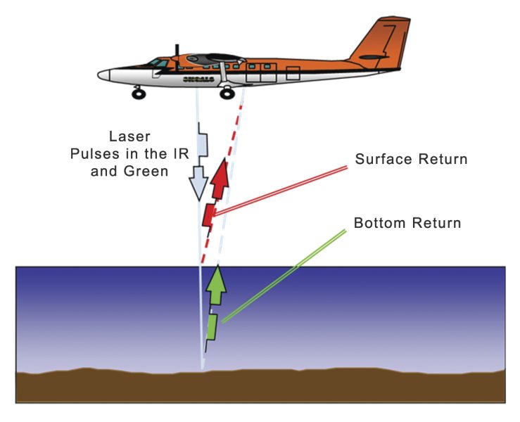
For bathymetry applications, i.e., high-resolution mapping of the sea bottom and coastal areas, a 532 nm laser source is often used because it represents the best compromise between high transmission in pure water and limited backscattering from submarine particulates. Figure 213 shows an application where two wavelengths are used in LiDAR bathymetry. In this case, an NIR pulse (typically at 1064 nm) is reflected from the water surface while 532 nm light penetrates the water surface and is reflected from the sea bottom.
Eye-safe lasers are becoming increasingly popular in high-performance compact LiDAR systems for civil and commercial applications. SWIR lasers operating at 1550 nm are generally more eye-safe at higher power levels and are typically used when solid bodies need to be detected, e.g. in topography mapping and obstacle avoidance. Furthermore, atmospheric transmission is quite good at this wavelength. Military applications also utilize these sources, as night vision devices are relatively insensitive to this wavelength. However, detection at 1550 nm requires the use of InGaAs or Ge photodetectors which are more expensive and have lower detectivity than Si detectors. Another disadvantage of this wavelength is that it experiences strong water absorption. This significantly reduces the reflectance from certain objects, such as snow and vegetation, and limits LiDAR usage.
Pulse Repetition Rate
The pulse repetition rate and pulse energy determine the applicable sampling rate of a LiDAR system. These parameters determine what will be the densely-spaced network of highly accurate geo-referenced elevation points produced by the system. High pulse repetition rates enable faster acquisition of data and/or higher point cloud density. The higher the point cloud density (typically given in points per m2), the better the achievable resolution with a LiDAR system. For instance, 4 points/m2 correlates to 0.5 m of ground sample distance. If pulses are strong enough, faster scanning can enable an aircraft to fly at higher altitude while still effectively mapping the terrain. This yields higher swath widths, which accelerates mapping throughput, thereby reducing time and flight costs.
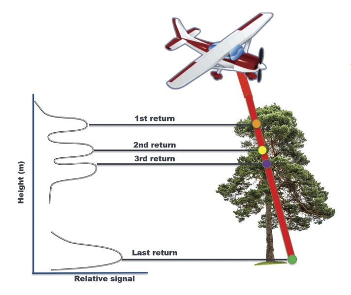
LiDAR system throughput has advanced considerably in recent years. Early commercial units were capable of operation at 10 kHz (10,000 points per second) and were large and bulky. Newer systems are more compact, lighter, and can process multiple laser returns in air, allowing for pulse rates to exceed 1 MHz. Multiple returns occur when a pulse strikes a target but is not completely reflected or absorbed, resulting in a portion of the pulse continuing to lower objects where it can also be reflected (see Figure 3). Multiple return systems can increase the amount of collected data significantly and enhance the ability to map 3D structures such as forest canopy, tree crowns, and other vegetation features.
Laser Pulse Width
The laser pulse width determines the range or vertical target resolution. This resolution (dR) can be determined by dR = cτ/2, where c is the speed of light in vacuum and τ is the pulse width (duration). For example, when τ = 2 ns, dR = 30 cm, which means that the distance between two objects must exceed this value to be accurately identified as separate targets. Current LiDAR sensors use laser pulse widths in the 2-5 ns range, mainly limited by the bandwidth of the receiver. The vertical range resolution can be significantly improved by full-waveform (FW) LiDAR systems, which image a scene by emitting laser pulses in a particular direction and capturing the entire temporal envelope of each echo. In such a method, FW systems capture more detailed physical information and characteristic properties of the 3D scenes compared to conventional LiDAR systems. However, the collected datasets are very large as there is a need to record the entire digitized backscattered laser pulses with a very high sampling rate (1-2 GHz).
Laser Power and Beam Divergence
The maximum distance from which data can be measured is generally important to LiDAR users. Factors affecting the maximum range are laser peak power, target surface diffuse reflectance, and the amount of ambient light coming from the target surface. The reflected laser power must be sufficient to overcome the detector's SNR and trigger the pulse detector. Detectors typically have some limiting threshold that is set to mask out noise from ambient light. Therefore, for high altitude mapping applications, there is a need for lasers that can generate high peak power pulses (in the tens of kW range) over a wide range of repetition rates (hundreds of kHz range).
The LiDAR minimum spot/footprint size at the target region is directly related to the flying height above the ground and the laser beam divergence. For example, for an aircraft height of 1000 m above ground and a beam divergence of 0.3 mrad, the spot size on the ground would be 30 cm. The same spatial resolution can be achieved (while doubling the throughput) if the plane height is increased to 2000 m and the beam divergence is reduced to 0.15 mrad. These relationships typically result in trade-offs. For instance, higher elevation requires larger pulse repetition rates (to maintain spatial resolution), but this typically results in a reduction in pulse energy which reduces system SNR. Moreover, lower divergence values require larger beam expansion optics due to the laser brightness limitation known as the etendue conservation law. Modifying the LiDAR transmission optics provides control over the target spot size and the laser radiance on the target surface. The latter affects the SNR because of the amount of reflected signal compared to the ambient sunlight illumination.
Spectral Width
As discussed above, 1064 nm is the most common wavelength for airborne LiDAR systems due to the laser/detector availability and high reflectance from common targets. One major limitation of this wavelength is the background noise created by the spectral irradiance of the sun. To improve the SNR in this wavelength regime, LiDAR receivers employ a narrow bandpass filter. It is therefore essential that the spectral width of the laser be sufficiently narrow (e.g., < 0.1 nm). Narrowband filters used in airborne LiDARs are often based on thin-film coatings which have proven to be robust enough to withstand the broad (and often harsh) set of environmental conditions.
Implementing these filters is important when working with narrow linewidth master-oscillator power-amplifier (MOPA) based pulsed lasers. In this MOPA architecture, the central wavelength is determined by a seeding laser source (often a laser diode) which determines the spectral characteristics of the emitted pulse. The linewidth can be tailored by choosing the right laser diode architecture and designing the subsequent amplification chain accordingly. The central wavelength is affected by the thermal conditions of the diode, such as temperature stabilization, drive current, and the pulse repetition rates. This can make wavelength control difficult, therefore the bandwidth of the filter must be made wide enough to accommodate wavelength shifts.
This requirement suggests that the bandpass filters used by LiDAR detection systems must be designed with a broad and uniform transmission spectrum. Additionally, sharp spectral edges are desired to maintain narrowband operation and optimally reduce spectral noise. By utilizing multilayer thin film coating techniques, it is possible to achieve these characteristics to optimize system performance. In typical applications, the laser is required to deliver over 90% of its pulse energy within a specified bandwidth of < 2 nm.
Efficiency, Footprint, and Weight
LiDAR systems are mounted on aircraft, UAVs, and even drones. Therefore, it is crucial to keep the laser source as compact, lightweight, and as efficient as possible. It also needs to be robust enough and perform under constantly changing environmental conditions, e.g., temperature, humidity, vibrations, shocks, repeated takeoff and landing events. This combination of parameters limits possible laser sources and makes fiber lasers a natural candidate. Their modularity, scalability, high efficiency, and inherent robustness make fiber lasers attractive for LiDAR applications over bulk solid-state laser systems.
LiDAR Applications
LiDAR Products

For additional insights into photonics topics like this, download our free MKS Instruments Handbook: Principles & Applications in Photonics Technologies
Request a Handbook