Optical Mirror Physics

Mirrors are arguably the most commonly-used optical components. They appear in small laboratory experimental set-ups, industrial applications, as well as large-scale optical systems. These components utilize reflection to redirect, focus, and collect light. Optical mirrors consist of metallic or dielectric films deposited directly on a substrate such as glass, differing from common mirrors, which are coated on the back surface of the glass. As a consequence, the reflective surface of an optical mirror may be subject to environmental conditions. This means that durability and damage resistance must also be considered when choosing a mirror as well as how well it reflects light at the wavelength of interest. This section introduces the physical concept of reflection and discusses the important attributes of the mirror as an optical component.

Reflection

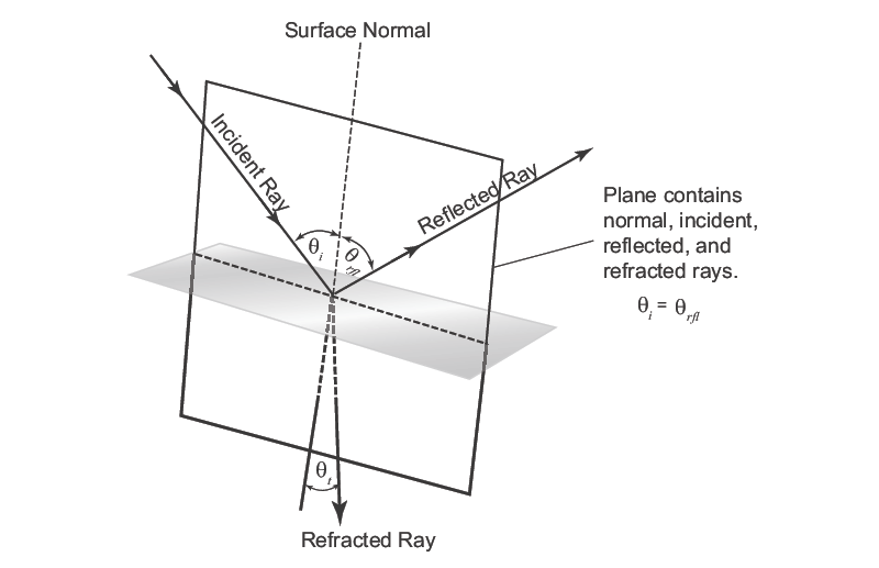
Generally, when light reaches a planar interface between two media (see Figure 1), a portion of it is reflected back into the original (incident) medium and a portion is transmitted and refracted into the second medium. Refraction of light is discussed in Optical Lens Physics. Absorption of the light in either medium is also possible, but non-absorbing media will be assumed here. The direction of the reflected light is governed by two laws. First, the incident ray, reflected ray, and the normal to the interface must lie in the same plane. In this plane of incidence, the angle of incidence (θi) is always equal to the angle of reflection (θrfl). Reflection can occur from smooth surfaces such as those found on mirrors (referred to as specular reflection) or from rough, uneven surfaces (called diffuse reflection or scattering). Although both obey the same laws of reflection, specular reflection leads to rays that reflect as a group at the same angle, whereas diffuse reflection occurs at different angles off randomly oriented surfaces. This enables specular reflection to perform the useful operations of redirecting light.
Illustration of the laws of reflection at a planar interface
Figure 1. Illustration of the laws of reflection at a planar interface.
The fraction of the incident light that is either reflected or transmitted at the interface is described by the Fresnel equations and depends on the angle of incidence as well as the index of refraction of the incident (n1) and refracting (n2) media. The fraction of the incident power reflected from the interface is called the reflectance or reflectivity (R), while the fraction refracted in the second medium is the transmittance or transmissivity (T). By assuming that both media are non-absorptive, the sum of R and T must be unity, thus allowing knowledge of one to provide information about the other. Furthermore, different linear polarization components of the incident light (see Polarization Control with Optics for details on polarization) possess different values of R and T. The Fresnel equations are greatly simplified for light at normal incidence, i.e., θi = 0, a situation of significant practical interest. At normal incidence, angular and polarization dependencies are removed from the formula for R (recall that T is complementary), leaving only the dependence on the indices of refraction:
Illustration of the laws of reflection at a planar interface
Equation 1. Reflectivity (R) is the fraction of the incident power reflected from the interface.
The index of refraction is a complex value with both real (associated with refraction) and imaginary (related to the transition absorption cross-section) components. Furthermore, there is a wavelength-dependence (or dispersion) associated with the index of refraction. Consequently, R is highly dependent on the materials making up either side of the interface, as discussed in the mirror characteristics section below.

Mirrors made up of planar surfaces, such as that shown in Figure 1, are important components for directing light through the proper path in an optical system. Such mirrors can be combined to form optical components known as retroreflectors or corner cubes. These components consist of three mirror surfaces all perpendicular to one another. Such a geometry enables 180 degrees reflection of the light, regardless of incidence angle, and therefore requires very little alignment compared to a single flat mirror. In addition to stationary mirrors, rapid redirection can be achieved by utilizing rotating planar mirror systems such as those found in scanners or on a smaller scale with micromirrors, which are used for switching in telecommunications and displays. Curved mirror surfaces (also called concave reflectors) can be exploited with the goal of collecting, focusing, and imaging light as illustrated in Figure 2. These mirrors possess an advantage over lenses (see Optical Lens Physics) in that they perform satisfactorily across a broad-wavelength range without requiring refocusing. The reason for this is that reflection occurs at the surface of these optics, rather than passing through the optic as is the case with a lens, and so the dispersion of the index of refraction does not come into play. Simple spherical reflectors can be used to collect radiation from a source at the focal point (located at half of the radius of curvature of the mirror) and reflect it as a collimated beam parallel to the axis. Since spherical mirrors possess spherical aberration (see Section III.A.3), a parabolic curved surface can be used instead to either collimate light from a focal point or focus light from a collimated beam (see Figure 2). Ellipsoidal surfaces can focus light from one focal point to another (see Figure 2).

Concave reflectors with different surface shapes allowing for light collection and focusing
Figure 2. Concave reflectors with different surface shapes allowing for light collection and focusing. A paraboloidal reflector reflects light from the focus into a collimated beam (left). An off-axis paraboloidal reflector refocuses a collimated beam off the mechanical axis (middle). Ellipsoidal reflectors reflect light from one focus to a second focus, usually external (right).

Mirror Characteristics

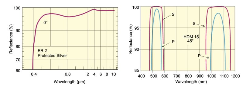
Selecting the proper mirror for an application requires consideration of a number of factors, including reflectivity, laser damage resistance, coating durability, thermal expansion of the substrate, wavefront distortion, scattered light, and cost. These mirror characteristics depend on the optical coating, the substrate, and the surface quality. The optical coating is the most critical component of a mirror as it dictates its reflectivity and durability. Processes for depositing high-quality optical coatings are discussed in Optical Coatings. Optical mirror coatings are typically made up of either metallic or dielectric materials. A common situation for mirror applications is when light is incident from air (n1 = 1) onto the optical coating material and so the reflectivity given by Equation (1) is dictated solely by the material’s index of refraction (n2). By virtue of their conductivity, metals have a complex index of refraction with a large imaginary part over a very wide wavelength range. This gives rise to a large reflectivity that is relatively insensitive to wavelength, which gives metallic mirrors their shiny appearance. Metallic coatings are usually made of silver, gold, or aluminum and the resulting mirrors can be used over a very broad spectral range (see Figure 3). Metallic coatings are relatively soft, making them susceptible to damage, and special care must be taken when cleaning. Mirrors with dielectric coatings are more durable, easier to clean, and more resistant to laser damage. However, as a consequence of their dispersive and predominantly real indices of refraction, dielectric mirrors have a narrower spectral reflectivity and are typically used in the VIS and NIR spectral region. There is greater flexibility in the design of dielectric coatings compared to metallic coatings (see Optical Coatings). When compared with metallic mirrors, a dielectric mirror can offer higher reflectivity over certain spectral ranges and can offer a tailored spectral response (see Figure 3).
Reflection spectra of silver metallic mirrors showing broadband reflectivity and dielectric laser-line mirror showing two narrow reflection bands
Figure 3. Reflection spectra of silver metallic mirrors showing broadband reflectivity (left) and dielectric laser-line mirror showing two narrow reflection bands (right).
Most substrates upon which the coatings are deposited are dielectric materials and these substrates control the thermal expansion and transmission properties of mirrors. Certain materials have lower thermal expansion coefficients, e.g., PYREX® borosilicate glass or fused silica, than others, e.g. N-BK7 optical glass, but the cost of the material and ease of polishing must also be considered. If light transmitted through the substrate is not required, the backside of the substrate is typically ground to prevent inadvertent transmissions. However, for transmissive mirrors, a substrate material with a homogenous index of refraction is important, e.g. fused silica.

Prior to depositing the optical coating, the substrate’s surface must be ground and polished to the proper shape (either planar or curved). The surface quality and flatness determine the fidelity of the mirror performance with the targeted application dictating the requirements for these parameters. Surface flatness is often specified in wavelengths, e.g. λ/10, over the entire usable area of the mirror. When preservation of the wavefront is critical, a λ/10 to λ/20 mirror should be selected, while less demanding applications can tolerate a λ/2 to λ/5 mirror with the associated reduction in cost. Surface quality is usually dictated by the severity of random localized defects on the surface. These are often quantified in terms of a “scratch and dig” specification, e.g. 20-10, with a lower value indicating improved quality and therefore lower scattering. For high precision surfaces, such as those found within the cavity of a laser, a scratch-dig specification of 10-5 may be required since it would yield very little scattered light. Surface polishing tolerances in terms of irregularity, surface roughness, and cosmetic imperfections are verified using state-of-the-art metrology equipment. These same parameters and procedures are used to assess the quality and flatness of other optical components such as lenses or windows.


MKS Semiconductor Handbook Cover

For additional insights into photonics topics like this, download our free MKS Instruments Handbook: Principles & Applications in Photonics Technologies

Request a Handbook