Calibrating Cornerstone Monochromators and MS260i Spectrographs
Grating installation and field calibration are typically performed at one of Newport’s manufacturing location, or by qualified field service personnel. The instructions provided in this section are for advanced users only and should be followed at the customer’s own risk. Newport suggests that monochromators be returned annually for service. In addition to verifying the calibration, the instrument would be fully inspected. Any refurbishment required, such as fresh lubrication on the worm gear, would be included in the servicing of the instrument.
Calibration Parameters
The following parameters are used by the instrument to determine the grating position. Each grating includes all three calibration parameters and are defined below.
- Calibration Factor
- Offset
- Zero
Calibration Factor: After performing a two-point calibration, the grating position with respect to two wavelengths is determined. It is easiest to understand the calibration factor by picturing a graph of the wavelengths vs. positions, where the calibration factor is the slope of the line connecting the two calibration points.
Offset: A wavelength offset is used to shift the wavelength position to either a higher or a lower wavelength. For example, if a HeNe laser operating at 632.8 nm is sent through a monochromator and the output is visible when the monochromator is set to 640 nm, an offset can be introduced.
Zero: All diffraction gratings installed in the instrument are mounted onto a rotating turret. This number indicates the angle of rotation, in radians, required to position the grating in the light path within the instrument. These values do not change for a CS130 monochromator. For a CS260 monochromator or MS260i spectrograph, either two or three gratings may be installed. The zero parameter for each grating remains the same unless changing from a double-grating configuration to a triple-grating configuration, or visa versa.
Resolution vs. Slit Width
All monochromators and spectrographs featuring fixed slit holders require fixed slits to be installed at both the input and output ports. Fixed slits are ordered separately, and should be the same size at the input and output ports. Micrometers adjustable slits allow for continuous variation of the width and height and should be set to the same width at all instrument ports.
When performing a calibration, it is important to use narrow slit widths in order to determine the spectral peak locations with the greatest accuracy. Spectral resolution is the ability to separate wavelengths, usually expressed as the Full Width Half Maximum (FWHM). It is calculated by multiplying the grating’s reciprocal dispersion in nm/mm by the slit width in mm. This calculation is valid at the grating’s blaze wavelength. For slit widths below 120 um, abberations begin to play a role. In those cases, the formula should be used as an approximation. The slit widths chosen should allow the monochromator to produce an output with the desired resolution.
Grating Alignment
A diffraction grating is bonded to a mount that is designed to fit specifically in Oriel’s monochromators and spectrographs. Each instrument has its own unique grating mounts. The mounts are designed so that adjustments its screws will adjust the direction of the light output in both the horizontal and vertical directions. Whenever a mounted grating is installed into the instrument, the grating assembly requires alignment.
A light source should be placed at the input of the instrument, with the slit width set to be as narrow as possible. The output slit, at the beginning of the alignment process, can be set to be wide. As the light path is aligned, the output slit should be gradually narrowed until it is the same width as the input slit.
Utilizing a Light Source & Detector
A calibration light source needs to be selected so that the spectral peaks are within the operating range of the diffraction grating. The detector being utilized must also have spectral coverage within the wavelength range of interest. When determining which wavelengths to use during calibration, it is generally easiest to select isolated peaks with high intensity. By stepping up or down the wavelength of the instrument in very small increments, these peaks may be located by observing the detector signal output. Various calibration light sources are available from Newport.
A variety of calibration line lamps are available which provide known spectral peaks with which to perform a calibration. The locations of these peaks and their relative intensities are available on Newport.com. Utilizing a laser is by the simplest light source to use when aligning the grating and performing the calibration. However, two laser lines are required to set the grating factor. A single laser may be used to determine an offset.
It is important to ensure the laser is perpendicular to the instrument’s input port and the laser is centered at the input slit. It should also be noted that the angle of any light source at the input of the instrument will adversely affect the calibration accuracy. To prevent this issue, it is recommended to use an integrating sphere.
When performing a calibration of an infrared grating, the spectral peaks of the calibration line lamps may not be located in the wavelength range of interest. In these cases, it is necessary to take advantage of a diffraction grating’s multiple orders.
Multiple Grating Orders
In general, when a monochromator is set for wavelength Λ, radiation at Λ/1, Λ/2, Λ/3 can also be present at the output. The denominator 1, 2, 3, etc. is called the order of diffraction. Radiation at Λ is called first order radiation, which is the desired wavelength when the monochromator is set to output Λ. Radiation at Λ/2 is called second order radiation, Λ/3 is called third order, etc.
All radiation at Λ/2, Λ/3, etc. can be collectively referred to as higher order radiation. As an example, when a 633 nm laser line passes through a monochromator, second order radiation will also be present at 316 nm (633/2). Conversely, radiation shall also be present at 1266 nm (633*2), 1899 nm (633*3), etc.
If these higher orders are outside of the detector’s operating range, they are not of concern in the calibration process. When they are within the detector’s operating range, they may be blocked by filters. In the case of IR gratings where spectral peaks are not available in the operating range of the grating, higher order radiation is utilized to perform calibration.
More information on grating physics and blocking higher order radiation is available on Newport’s technical notes and tutorial web pages.
Setting the Wavelength Offset
A wavelength offset is used to shift the wavelength position to either a higher or a lower wavelength. For example, if a HeNe laser operating at 632.8 nm is sent through the monochromator and the output is visible when the monochromator is set to 640 nm, an offset can be introduced.
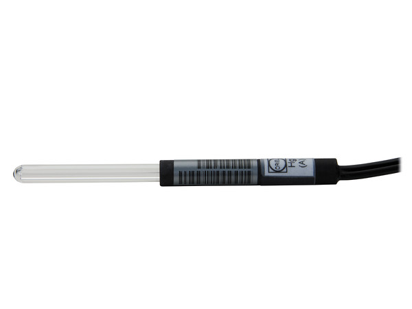
When performing this procedure, it is necessary to use a light source with a known spectral line appearing within the operating range of the grating. Oriel offers a number of pencil calibration lamps for this purpose, such as the model 6035 HgAr lamp. Another line source such as a laser may also be used. Always be sure to follow the appropriate safety precautions when dealing with any light source.
Procedure:
- Select a radiation source that has at least one narrow spectral line in the wavelength region of interest.
- Select a detector with an operating range appropriate for the spectral line.
- Focus the radiation onto the entrance slit (the monochromator is F/3.9). Note that a narrower slit provides greater resolution.
- Ensure the focused beam is parallel to the monochromator’s optical axis.
- Command the monochromator to select the grating for which the offset is to be applied to.
- Use the STEP command to move the grating position until the spectral line is visible at the output.
- Use the CALIBRATE command to enter the exact wavelength of the spectral line. The Cornerstone wavelength offset has now been entered into memory. This offset applies to all other wavelength positions when using this grating.
- Repeat the process for the second and third gratings, if required. Depending on the configuration, the monochromator may have two or three gratings installed.
Determining the Grating Calibration Factor
The following procedure allows advanced users to perform a two-point grating calibration.
Procedure:
- Select a radiation source that has at least two narrow spectral lines in the wavelength region of interest.
- Select a detector with an operating range appropriate for the spectral lines.
- Focus the radiation onto the entrance slit (the monochromator is F/3.97). Note that a narrower slit provides greater resolution.
- Ensure the focused beam is parallel to the monochromator’s optical axis.
- Command the monochromator to select the grating to be recalibrated.
- Use the STEP command to move the grating position until the first spectral line is visible at the output.
- Note the wavelength at which this first spectral line peak appears.
- Use the STEP command to move the grating position until the second spectral line is visible at the output.
- Note the wavelength at which this second spectral line peak appears.
- Use the formula to calculate the new Grating Factor.
- Use the utility software to enter the new Grating Factor. The GRATINGn FACTOR command may also be used
- Repeat the process for the second and third gratings, if required. Depending on the configuration, the monochromator may have two or three gratings installed.
| Spectral Line | Observed Peak | |
|---|---|---|
| Wavelength 1 | 546 | 577 |
| Wavelength 2 | 365 | 372 |
FACTOR = | L1 – L2 | / | P1 – P2 |
FACTOR = |546 – 365| / |577 – 372| = 181 / 205 = 0.8829268
Determining the Grating Zero Parameters
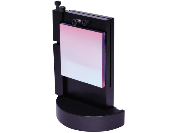
The grating zero parameter for each grating is determined by the monochromator or spectrograph model and number of gratings installed into the instrument. It is important to understand the type of grating mount used in the CS260 monochromators and MS260i imaging spectrographs. Although only one or two gratings may be installed, they still may be mounted into a double or triple style grating mount. The zero parameters must match the values noted in the table below.
| Grating Mount Variations | ||
 |
 |
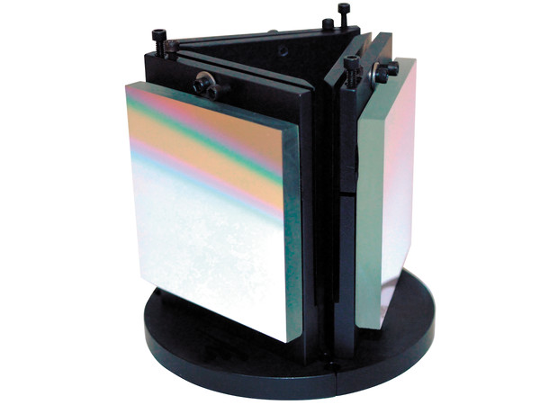 |
| CS130 Grating | CS260 and MS260i Double Grating Mounts | CS260 and MS260i Triple Grating Mounts |
| Zero Parameter Values | |||
|---|---|---|---|
| Model | Grating Position | Zero Parameter Value | Instrument Configuration |
| CS130 Monochromators | Grating 1 | 0.0872665 | All configurations |
| Grating 2 | 3.2288589 | ||
| CS260 Monochromators and MS260i Imaging Spectrographs |
Grating 1 | 0.0872665 | Triple grating mounts installed |
| Grating 2 | 2.1816616 | ||
| Grating 3 | 4.2760567 | ||
| CS260 Monochromators and MS260i Imaging Spectrographs |
Grating 1 | 0.0875665 | Double grating mounts installed |
| Grating 2 | 3.2288591 | ||
| Grating 3* | 3.2288591 | ||
* Although a third grating cannot be physically installed when using double grating mounts, the instrument's firmware always stores a value for Grating 3.
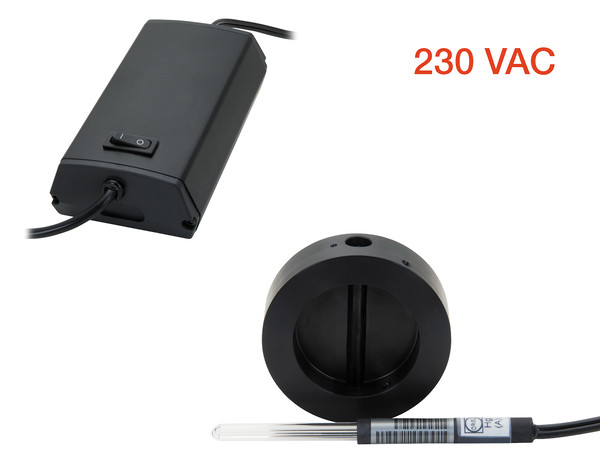
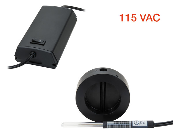
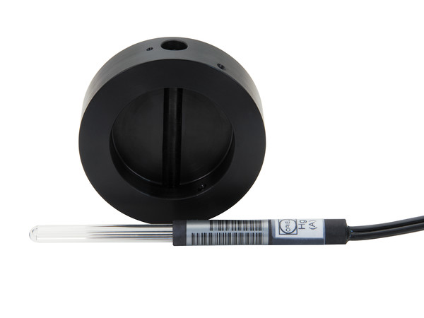
Calibration Accessories
We carry a full range of Pencil Style Calibration Lamps and accessories to fit most applications. A calibration kit includes the popular Hg(Ar) calibration lamp, power supply and an enclosed holder which fits directly onto the input slit flange of the monochromator or spectrograph. Click on the lamp models to learn more about the spectral peaks produced by each model.