Calculating the Output Power of Collimated Beams

You can estimate the power in the collimated beams* at any wavelength or in any wavelength range from our Series Q, Apex, or Research Lamp Housings with any of our light source lamps. The procedure is similar to compute the output from the 7340 and Apex Monochromator Illuminators and PhotoMax™ (which produce focused outputs), but you must factor in the reflectance of the mirror.

* This discussion covers the output from the condenser when operated to produce a collimated beam. You can produce more output in a diverging beam by moving the condenser in, and less by moving it out.

At a Single Wavelength

To find the total output power per nm at any wavelength for any of our Lamp Housings simply:

  1. Read the value of the irradiance from the curve for the lamp; the value will be in mW m-2 nm-1.
  2. Find the conversion factor for your Lamp Housing and condenser type (listed in Tables 1 and 2), and multiply this by the value from 1. The result will be in mW nm-1.
  3. Multiply the result by 1.6 when a rear reflector is used.

Table 1: Conversion Factors for Series Q, and 250 and 500 W Research Housings

Condenser Type
F/#
Lens Material Spectral Range Condenser Aperture (mm) Conversion Factor*
F/1.5 Fused Silica 200 - 2500 nm 33 0.06
F/1 Fused Silica 200 - 2500 nm 33 0.11
F/0.85 Pyrex® 350 - 2000 nm 33 0.13
F/0.7 Glass/Fused Silica 350 - 2000 nm 69 0.18
F/0.7 Fused Silica 200 - 2500 nm 69 0.20

* Measured at 500 nm

Table 2: Conversion Factors for 1000 and 1600 W Research Housings

Condenser Type
F/#
Lens Material Spectral Range Condenser Aperture (mm) Conversion Factor*
F/1 Fused Silica 200 - 2500 nm 48 0.13
F/0.7 Glass/Fused Silica 350 - 2000 nm 69 0.18
F/0.7 Fused Silica 200 - 2500 nm 69 0.20

The Rear Reflector

The rear reflector captures backwards emitted radiation, and when properly adjusted, reflects it back through the source to contribute to the total output. This applies particularly to arc lamps, which are transparent at most wavelengths. The factor of 1.6 decreases below 350 nm, to about 1.2 at 250 nm.

You do get additional output from the QTH Lamps, but you must displace the re-imaged filament when using our closed packed planar filaments. This may limit the usefulness of the additional output. Re-imaging onto the filament does increase the collimated output a little and changes the power balance of the system. You cannot use a rear reflector with our Deuterium Lamps.

Where Did the Conversion Factors Come From?

We measure the output of our lamp housings and use the measured irradiance curves to determine the conversion factors at 500 nm. You can, in principle, use the irradiance curves to calculate factors for each condenser for an ideal point source, as we know the collection geometry and transmittance. Since our lamps are neither point sources nor truly isotropic, the tabulated empirical values are better. We list the values at 500 nm. Values at other wavelengths, within the transmission range of the condenser, will be similar.

Example 1

Find the output at 405 nm from the 66924 Arc Lamp Source operating the model 6293 1000 W Hg(Xe) lamp; see Arc Lamp Spectral Irradiance Data for this lamp curve. The value at the peak of this line is:

1000 mW m-2 nm-1. The conversion factor for the F/1 lens in this source is 0.13.

Therefore, the output at 405 nm for the source will be:

1000 x 0.11 = 130 mW nm-1

This lamp housing includes a rear reflector. This will increase the output by ca. 60%, to give 208 mW nm-1.

Total Power in a Specified Spectral Range

To find the total output power in a wavelength range:

1. Find the curve for the particular lamp.

2. Calculate the total irradiance in your wavelength interval, λ1 to λ2, from the graph. The total is the area under the curve between λ1 to λ2. The result will be in mW m-2.

3. Multiply the total irradiance in mW m-2 from Step 2, by the conversion factor for your Oriel® Lamp Housing and condenser. The result will be in mW.

4. Multiply the output by 1.6 when a rear reflector is used.

Example 2

Find the output from 520 - 580 nm from the 6255 150 W xenon lamp.

1. From the graph, the irradiance over this range is approximately 20 mW m-2 nm-1. The range is 60 nm, so the total irradiance is 60 x 20 = 1200.

2. The conversion factor for the efficient Aspherab® is 0.18, so the total output in this spectral range is 1200 x 0.18 = 216 mW.

3. Since this lamp housing includes a rear reflector, and these increase the output by ca. 60% when using an arc lamp, the final output will be close to 346 mW.

Monochromator Illuminators and PhotoMax™

Below we list the conversion factors at 500 nm for the 7340 and 7341 Monochromator Illuminators, Apex Monochromator Illuminators and PhotoMax™. You should multiply the factor from the tables by the reflectance at the wavelength of interest, and divide by the reflectance at 500 nm. The conversion factor assumes no window in the PhotoMax™ (The 7340 and Apex Monochromator Illuminators do not use windows), so you should multiply by 0.92 if you use a window.

Table 3: Conversion Factors for PhotoMax™ at 500 nm

Reflector F/# Reflector Coating Conversion Factor
4.4 Rhodium or AIMgF2 0.8
3.7 Rhodium or AIMgF2 0.9

Table 4: Conversion Factor for Monochromator Illuminator at 500 nm

Output F/# Reflector Coating Magnification Conversion Factor
3.75 AIMgF2 1.75 0.038

Table 5: Conversion Factor for Apex Monochromator Illuminator at 500 nm

Output F/# Reflector Coating Magnification Conversion Factor
3.75 AIMgF2 1.75 0.038

Example 3

Find the output from PhotoMax™ at 275 nm operating the 6256 150 W Xe lamp. The PhotoMax™ has a fused silica window, the 60130 Beam Turner with the 60141 UV Dichroic, and is configured with an F/3.7 Reflector.

The lamp irradiance at this wavelength is 15 mW m-2 nm-1

The tabulated conversion factor for 500 nm is 0.9. We multiply this by 0.96, the ratio we estimated by comparing the reflectance of the AlMgF2 coating at 500 and 275 nm. We also need to multiply by 0.92 for the window transmission. So the output is:

15 x 0.9 x 0.96 x 0.92 = 12 mW nm-1 at 275 nm.

The reflectance of the dichroic is 0.83 at 275 nm, so the final output is:

12 x 0.83 ~ 10 mW nm-1.

Example 4

Find the output from the 7340 Monochromator Illuminator at 600 nm operating the 6332, 50 W QTH lamp.

The irradiance from the 6332 is 10 mW m-2 nm-1 (see QTH Lamp Spectral Irradiance Data for lamp irradiance data). Since the reflectance of AlMgF2 is the same at 500 and 600 nm, 95%, we multiply the 7340 conversion factor, 0.038, by 95.

The total output from the 7340 is:

10 x 0.038 x 0.95 = 0.36 mW nm-1 at 600 nm.

Pulsed Sources

Since we monitor the repetition frequency, we get the total spectral energy density at 0.5 m in mJ m-2 nm-1 due to the average pulse, by dividing the number of pulses per second.

The validity of the measurement technique depends on the fidelity of the integration by the CCD. Are short high power pulse events properly integrated? All our tests using special high speed chopper wheels to generate pulses of different duration from a continuous source show that our CCD indeed produces valid calibration data.

Calculating Source Output

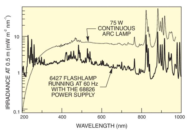
The Series Q Pulsed Systems use the popular Series Q Housing, and total output is calculated just as a CW source is, by looking at the spectral irradiance curves and multiplying the irradiance in the desired bandwidth by the factor listed in Table 1.

Irradiance of 6427 Flashlamp, and 75 W DC arc lamp
Figure 1. Irradiance of 6427 Flashlamp, and 75 W DC arc lamp.