Motion Control Systems

An automated motion control system consist of three main components: a motion controller, a motor driver or amplifier, and a motion device. The primary purpose of a motion controller is to control the dynamics of the motion device. The motor driver converts the command signals from the motion controller into power signals required to move the motor. The motion device is any mechanical device that provides motion and is actuated by a motor. Such motion devices typically contain feedback devices to provide information such as position and velocity to the motion controller. In this section, motion devices are discussed first and mainly in the context of manual positioning. This discussion is equally applicable to automated positioning and motorized drivers and electronic controllers are then detailed.

Motion Devices

Motion devices are mechanical positioning devices such as linear translation stages, rotation stages, and linear actuators. While the specifications of a stage or actuator are important selection criteria, they may not be exhaustive enough or directly applicable for each application. For this reason, it is important to have sufficient understanding of the inherent abilities of the components that make up a stage. This section provides a brief discussion of the most common components used in high precision positioning equipment with their pros and cons. The main components of a motion device are the materials used for the body construction, the mechanism that enables translation or rotation, and the drive mechanism.

Each material used for mechanical components in motion control has its own unique set of advantages and disadvantages. Table 1 provides a summary of the properties of the most commonly used materials in motion mechanics. Stiffness is a measure of the amount of force required to cause a given amount of deflection. Young's modulus is a material-dependent constant that quantifies the stiffness with large values indicating greater stiffness. Thermal expansion is the change in size or shape of an object, such as a stage, due to a change (increase or decrease) in temperature. When temperature change across a component is non-uniform, such as when a heat source like a laser diode is present, a material which does not dissipate heat may be susceptible to distortions caused by thermal gradients. In this case, the relative thermal distortion, i.e., ratio of the coefficients of thermal expansion to thermal conductivity, becomes important with lower values being preferred. Aluminum is a lightweight material, with good stiffness-to-weight ratio, and has low thermal distortion. It is also fast-machining, cost-effective, and does not rust. However, anodized surfaces are highly porous, making them unsuitable for use in high vacuum. Steel has very good stiffness, good material stability, low thermal expansion, and is well suited to high vacuum applications. Machining of steel is much slower than aluminum, making steel components considerably more expensive. Corrosion of steel is a serious problem, but stainless steel alloys can minimize these problems. Brass is a dense material and fast machining. The main use of brass is for wear reduction where it can be used to avoid self-welding effects with steel lead-screws or shafts. Brass has a less desirable stiffness-to-weight ratio and does not have ideal thermal expansion or thermal conductivity properties. Granite is an extremely hard material allowing polishing to very flat surfaces, which is beneficial in positioning accuracy and repeatability of a total system. Granite also has a very low thermal expansion coefficient. However, for large structures and table surfaces, the mass of a granite structure can become impractically large.

Parameter  Steel   Aluminum Brass  Granite 
 Young's Modulus (stiffness), E, Mpsi (GPa)  28 (193)  10.5 (72)  14 (96)  7 (48)
 Thermal Expansion, a (µin/in/°F)  5.6  12.4  11.4  4
 Thermal Conduction, c (BTU/hr-ft-°F)  15.6  104  67  2
 Specific Stiffness, E/ρ  101 (25.4)  108 (27.7)  45.6 (11.3)  70 (17.8)
 Relative Thermal Distortion, a/c  0.36  0.12  0.17  2
 Density, ρ, lb/in3 (gm/cc)  0.277 (7.6)  0.097 (2.6)  0.307 (8.5)  0.1 (2.7)

Table 1. Properties for common stage materials.

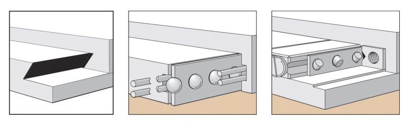
The load and trajectory performance of a translation or rotation stage is primarily determined by the type of bearing or flexure used. Bearings are the preferred mechanism since they provide smooth low-friction rotary or linear movement between two surfaces. They are the primary elements that determine the runout errors of a stage, define the stiffness, and the static load capacity of a stage. Bearings employ either a sliding (dovetail) or rolling action (ball or crossed-roller) as shown in Figure 1. In both cases, the bearing surfaces must be separated by a film of oil or other lubricant for proper performance. Dovetail slides are primarily used for manual positioning and consist of two flat surfaces sliding against each other. They can provide long travel, and have relatively high stiffness and load capacity. However, they do possess high stiction, and the friction varies with translation speed, which makes precise control difficult and limits sensitivity. Ball bearing slides reduce friction by replacing sliding motion with rolling motion. Balls are constrained by vee-ways or hardened steel rods and the friction is very low, resulting in extremely smooth travel. Since the contact area available to transmit loads is smaller in vee-groove bearing ways, ball bearings have a lower load capacity than crossed-roller or other bearings. In order to carry the same sized load, the balls would need to be larger in diameter or be greater in quantity. Crossed-roller bearings offer all of the advantages of ball bearings but with higher load capacity and higher stiffness. This is a result of replacing the point contact of a spherical ball with the line contact of a cylindrical roller. Due to the averaging characteristic of line contacts, angular and linear deviations are generally lower than those found in ball bearings. However, crossed-roller bearings require more care during manufacture and assembly resulting in higher costs. A flexure mechanism uses the elastic deformation of a material (typically a high-strength steel spring) to provide translation. This mechanism requires no lubrication and is virtually free of the stiction normally associated with bearings. However, when used in a translation stage, travel range is limited to just a few millimeters. Also, care must be taken so that permanent deformation does not occur, causing reduced functionality. In addition to these mechanical bearings, air bearings can also be used which provide a low-friction interface via a thin film of pressurized gas.

Different types of bearing mechanisms allowing for stage motion:  dovetail, ball bearing slide, and cross-roller bearing
Figure 1. Different types of bearing mechanisms allowing for stage motion: dovetail (left), ball bearing slide(middle), and cross-roller bearing (right).
A stage can be driven directly by a motor (see below) or indirectly based on different mechanical systems (see Figure 2). A popular technique for moving loads is to use the axial translation of a nut riding along a rotating screw. Lead screws use sliding contact, so their wear rate is directly proportional to usage. The advantages of lead screws include self-locking capability, low-noise motion, low initial costs, ease of manufacture, and a wide choice of materials. In order to eliminate possible backlash between the screw and the nut, the nut needs to be preloaded to the screw via an external spring, gravitational forces (applicable only to vertical use), or by a double nut with a spring in between. Recirculating ball screws are essentially lead screws with a train of ball bearings riding and rolling between the screw and the nut in a track. The primary advantage of ball screws is less screw heating, which can impact the stageÕs repeatability and accuracy. Also, because of the reduced friction, most ball screw stages can run at higher speeds and can perform smaller incremental motions compared to lead screw-driven stages. The large number of mating parts makes tolerances critical, thus increasing manufacturing costs. Also, ball screws generate more noise than lead screws due to the recirculating balls in the nut. The worm gear system transforms rotary motion from one plane into another plane by meshing a screw (worm) with a gear (worm wheel). As the screw is turned, the worm threads mesh with the gear, causing it to rotate. Worm drives are commonly used as a drive system for rotation stages and allow very low-profile design. In order to eliminate backlash, the worm and the worm wheel need to be in perfect contact with each other, which requires a sophisticated worm preloading system with high transversal stiffness.
Different mechanisms for indirectly driving a stage: lead screw, ball screw, worm drive
Figure 2. Different mechanisms for indirectly driving a stage: lead screw (left), ball screw (middle), worm drive (right).
Actuators (see Figure 3) also allow for indirectly driving a stage but are typically externally coupled and therefore, provide flexibility in terms of matching a particular stage with the desired drive mechanism. Manual actuators are simple, low-cost options for positioning and can be described as a high sensitivity lead screw with a knurled knob. Unlike the lead screw system described above, the nut of the screw is fixed to the stage body, and the adjustment screw itself moves back and forth. Springs press the carriage against the screw tip to make good contact and to preload the screw and eliminate backlash. Micrometer heads are the adjustment mechanism of choice if accurate position read-out or repeatable positioning is needed. Standard metric micrometer heads feature a scale in units of 10 µm but, with an additional vernier, can reach a resolution of 1 µm. When resolution of much less than one micron is needed, a differential screw is recommended. These devices use the difference between two screws of nearly the same pitch to produce very fine motion. Motorized linear actuators provide the ability to motorize manual linear translation stages for remote and/or computer control. Such actuators can either use the lead screw mechanism described above or can utilize the piezoelectric effect, which exploits interactions in certain crystalline materials to produce mechanical movement when an electric field is applied. These piezo actuators can achieve resolution of a few tens of nanometers and are sometimes referred to as nanopositioners. This increased resolution typically comes at a cost of reduced speed and/or travel range.
Various types of actuators including a manual actuator, a micrometer, and motorized actuators.
Figure 3. Various types of actuators including a manual actuator (left), a micrometer (middle), and motorized actuators (right).

Motorized Drivers

A motion device can be electronically controlled through either a direct or indirect motorized drive system. Common indirect drive systems for linear and rotary stages are based on the lead screws, ball screws, and worm drives discussed in the previous section. Shaft couplings, transmission belts, and gearboxes are often located between the drive system and the driving motor. These components affect system dynamics such as speed and torque capacity, but can also introduce backlash and hysteresis. The two most-common motors used for indirect drive systems are brushed DC motors and stepper motors. A brushed DC motor consists of a rotor placed in a magnetic field, which causes rotation when current is applied to the motor windings. The rotational speed is proportional to the applied voltage, while the torque is proportional to the current. DC motors are best characterized by their smooth motion and high speeds. A stepper motor operates using the basic principle of magnetic attraction and repulsion. Steppers convert digital pulses into mechanical shaft rotation. The amount of rotation is directly proportional to the number of input pulses generated, and speed is proportional to pulse frequency. One difference between a DC and a stepper motor is that when a voltage is applied to a DC servo motor, it will develop both torque and rotation. However, when a voltage is applied to a stepper motor, it will develop only torque. For the stepper motor to rotate, the current applied must be commutated or switched. Stepper motors are often used in open-loop control systems, a low-cost alternative to closed-loop DC servo systems. The pulse count is a good indicator of position, and stepper motors work reliably when used within their specified torque and speed range. However, the motion of a stepper motor becomes unpredictable outside of its specified range and skipping steps, extra steps or motor stalling can result. Stepper motors typically develop torque almost instantaneously, faster than with a DC brush motor. Hence, stepper motor-driven stages can deal with mechanical stiction better than DC motor-driven stages that often generate position overshoots when the motor torque exceeds the stiction.
Components for connecting the drive system and the driving motor, including a belt drive and a flexible shaft coupling
Figure 4. Components for connecting the drive system and the driving motor, including a belt drive (left) and a flexible shaft coupling (right).
In direct drive systems, the motor is directly coupled to the motion, with no screw or transmission system in between. The most common high-precision direct drive systems feature either a brushless linear motor for linear stages or a brushless torque motor for rotation stages. A linear motor consists of a permanent magnet assembly which establishes a magnetic flux, and a coil assembly which generates a force proportional to coil current. Linear motors have become very important components of precision positioning systems, with numerous advantages over traditional mechanical actuators such as ball screws. These systems typically provide higher quality, frictionless motion, and higher speeds and acceleration.

A motor driver receives input signals from a controller and converts them to power to drive a motor. A motor driver can be a simple amplifier or it can be an intelligent device that can be configured through software for varying operational parameters. Different motor drivers support the different types of motors used in motion control. The stepper motor driver receives input signals from the motion controller commanding it to step the motor to a commanded position. The driver then applies current to the stepper motor windings in order to move the stepping motor to the next step or increment. Drivers for DC motors simply convert a -10 V to +10 V analog control signal from the motion controller to a usable current to drive the motor. Most brushless DC motor drivers are simple amplifiers that convert control signals from the motion controller to a usable current to drive the motor, with the motion controller providing the motor commutation.

Electronic Controllers

In a motion system, the controller is used to manipulate stages and actuators so that they move or stop in a desired manner. Common motion systems use three types of control methods: position control, velocity control, and torque control. Each control method is based on a feedback device whose basic function is to transform a physical parameter, e.g., a scale reading, into an electrical signal for use by the controller. Most motion systems use the position control method. The purpose of the motion controller in these systems is to command a motor so that the actual position of the moving mechanism tracks the desired position specified by a preplanned trajectory. In this case, the primary feedback device is an encoder which directly monitors the position and provides the motion controller with actual displacement information. Typically, this is done optically by detecting light passing through a series of accurately-spaced slits in a metal or glass disc (see Figure 5). Velocity control is used in applications where velocity regulation is of primary importance, such as in spindles or conveyor belts. In these applications, the primary feedback device is a tachometer. Torque control is used in applications such as robotics where the torque applied by end-effectors must be controlled accurately in order to grasp or release objects. In these applications, the primary feedback device is a torque/force sensor such as a strain gauge.
Example of a linear steel scale encoder that ensures positioning with accuracy of ± 1 µm
Figure 5. Example of a linear steel scale encoder that ensures positioning with accuracy of ± 1 µm.
While the main objective of a motion controller is to control a motion device, many advanced motion controllers provide additional functions such as:
  • Trajectory generation for moving devices from one point to another or for coordinating the motion of multiple devices
  • An interface to let users configure and command the motion system to perform various tasks
  • Monitoring end-of-travel limits, amplifier faults, feedback errors, etc. for safety of the system
  • Digital input/output lines to synchronize external events to motion or vice versa
  • Memory for storing and running on-board motion programs

Furthermore, the output of the motion controller can be configured depending upon the type of motor used to move a motion device.


MKS Semiconductor Handbook Cover

For additional insights into photonics topics like this, download our free MKS Instruments Handbook: Principles & Applications in Photonics Technologies

Request a Handbook