How to Estimate Angular Motion of a Tilt or Rotation Stage with Respect to the Linear Translation of the Actuator
Introduction
One of the most common questions asked of our Opto Mechanical Specialists regarding the kinematic and gimbal optical mounts as well as the rotation and tilt stages is
“What linear travel distance on the micrometer, adjustment screw or motorized drive corresponds to a given angular motion of the stage or optical mount?”
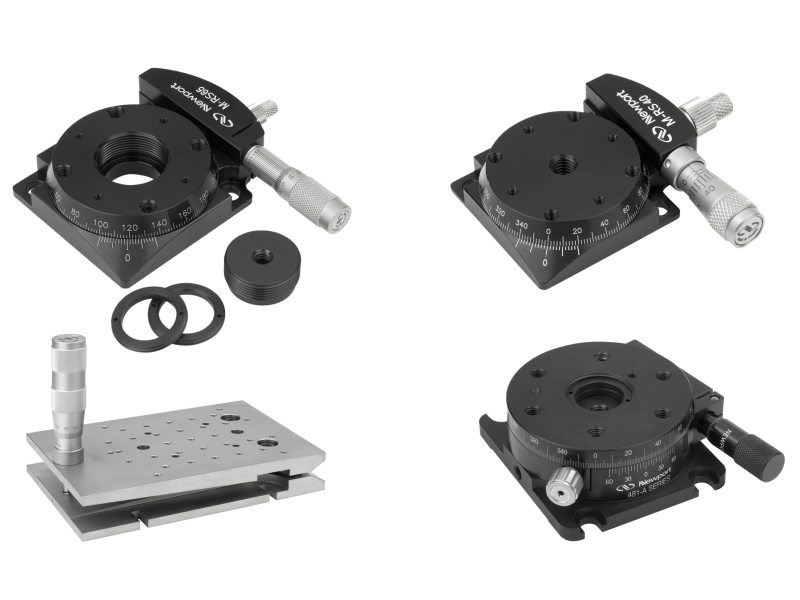
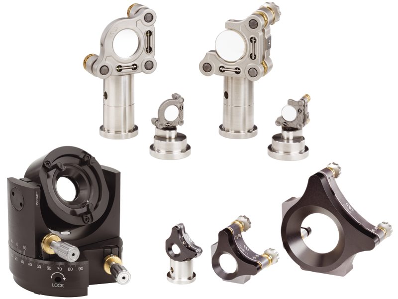
For rotation stages that provide a Vernier scale directly on the stage body – such as the 481-A, RS65 and RS40 – the angle of motion can be read on the scale. In the case of the 605-2 and 605-4 full range gimbal mounts, a scale is provided on the body for the azimuthal angle (but not for the elevation angle). But for all other kinematic, gimbal and tilt mounts that Newport offers, no scale is provided on the mount, so a different method to determine angular motion is needed.
Newport’s manual mounts and stages are not calibrated together with their actuators. This is due to the fact that the actuators are often easily removable or interchangeable. Consequently, removing, interchanging, or adjusting the position of the actuator in the mounting block on the stage would render any calibration void. However, it is possible, when needed, to use a simple trigonometric calculation to approximate the answer.
Method
In order to approximate the angular distance traveled when no scale is provided, knowledge of (1) the lever arm(s) of the mount and (2) the distance traveled on the actuator (micrometer, adjustment screw or motorized drive) is required. Distance can be easily read off of a micrometer. Adjustment screws, on the other hand, have no distance indicators. In order to determine the distance traveled per full turn for a linear adjustment screw, divide 1 inch by the number of threads per inch (TPI) of the screw. (A table of the lever arms for many of Newport’s products is provided at the end of this technical note.)
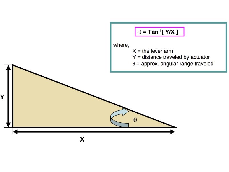
Once you have the lever arm and distance traveled, you will have obtained two sides of a right triangle. Using this specification and the calculation for the inverse tangent, you can approximate the angle traveled as follows.
Tables
The following are tables containing the lever arm specifications for many of Newport Corporations current rotation, tilt, kinematic and gimbal mounts.
Rotation Stages
| Model Number | Lever Arm | Angular Motion with 1µm Actuator Travel |
|---|---|---|
| RS40 | 0.98 in. | 8.3 arc sec |
| RS65 | 1.50 in. | 5.4 arc sec |
| 481-A | 1.27 in. | 6.4 arc sec |
Goniometric Stages
| Model Number | Lever Arm | Angular Motion with 1µm Actuator Travel |
|---|---|---|
| 561-GON | 1.28 in. | 6.3 arc sec |
| GON40-U | 1.07 in. | 7.6 arc sec |
| GON40-L | 1.86 in. | 4.4 arc sec |
| GON65-U | 2.75 in. | 3.0 arc sec |
| GON65-L | 3.93 in. | 2.1 arc sec |
Tilt Stages
| Model Number | Lever Arm | Angular Motion with 1µm Actuator Travel |
|---|---|---|
| TGN80 | 3.94 in. | 2.1 arc sec |
| TGN120 | 5.91 in. | 1.4 arc sec |
| TGN160 | 7.87 in. | 1.0 arc sec |
| 562F-Tilt | 2.94 in. (Vertical Actuator) 1.45 in. (Horizontal Actuator) |
2.8 arc sec 5.6 arc sec |
Kinematic Mounts
| Model Number | Lever Arm | Angular Motion with 1µm Actuator Travel |
|---|---|---|
| U50-A/P | 0.69 in. | 11.8 arc sec |
| U100-A/P | 1.50 in. | 5.4 arc sec |
| U200-A/P | 2.25 in. | 3.5 arc sec |
| U300-A | 3.25 in. | 2.5 arc sec |
| U100-AC | 1.50 in. | 5.4 arc sec |
| U200-AC | 2.38 in. | 3.4 arc sec |
| U300-AC | 3.25 in. | 2.5 arc sec |
| U400-AC | 4.25 in. | 1.9 arc sec |
| U500-AC | 4.25 in. | 1.35 arc sec |
| U600-AC | 4.75 in. | 1.21 arc sec |
| U800-AC | 6.25 in. | 0.85 arc sec |
| V100 | 1.50 in. | 5.4 arc sec |
| P100-A | 1.50 in. | 5.4 arc sec |
| P100-P | 0.69 in. | 11.8 arc sec |
| MM-050 | 0.31 in. | 26.2 arc sec |
| MM-075 | 0.48 in. | 16.9 arc sec |
| SN050 | 0.68 in. | 11.9 arc sec |
| SN100 | 1.50 in. | 5.4 arc sec |
| SS050 | 0.68 in. | 11.9 arc sec |
| SS100 | 1.50 in. | 5.4 arc sec |
| 625-RC6 | 2.55 in. | 3.2 arc sec |
Gimbal Mounts
| Model Number | Lever Arm | Angular Motion with 1µm Actuator Travel |
|---|---|---|
| 605-2 | 1.25 in. | 6.5 arc sec |
| 605-4 | 2.00 in. | 4.1 arc sec |
| U50-G | 0.88 in. | 9.2 arc sec |
| U100-G | 1.38 in. | 5.9 arc sec |
| U200-G | 2.50 in. | 3.2 arc sec |
| SL8A | 2.28 in. | 3.6 arc sec |
| SL15A | 4.25 in. | 1.9 arc sec |
| SL20A | 4.92 in. | 1.7 arc sec |