Motorized Linear Translation Stage Selection Guide
The Widest Range of Precision Linear Stages Offered in the Industry
Motorized Linear Stages from Newport are designed and built using many decades of experience in providing solutions to many markets including research and academia, industrial, semiconductor, aerospace and defense. We also offer Nanopositioning Linear Stages based on piezo motor technology and Custom Multi-Axis Stack Solutions.
Motorized Linear Stage Basics
A motorized linear translation stage is used to precisely position an object along a single axis. Motorized linear stages include a moving platform and stationary base joined by a bearing system. Position is controlled electronically with the use of a motion controller. Motorized stages are preferred for high load/high speed applications, as well as applications where manual adjustment may be difficult. See Motion Basics and Standards for more information. We also offer Manual Linear Translation Stages that can be positioned using a micrometer head, adjustment screw or linear actuator.
Motor Types
The motor of a stage has a significant impact on its capabilities, performance and price. Newport offers a variety of motor types – stepper motors, DC motors, linear motors and piezos – within our standard products to best meet your application and budget. Other factors such as type of bearing, construction material, and position feedback also affect stage performance, but presented in this table is a general summary of performance by motor type:
| Motor Type | Travel | Speed | Resolution | Repeatability | Load | Price |
|---|---|---|---|---|---|---|
| Linear Motor | Long | Fast | High | High | High | $$$ |
| Brushless DC | Medium | Medium | Medium | High | High | $$ |
| DC Motor | Medium | Medium | Medium | Medium | High | $$ |
| Stepper Motor | Medium | Medium | Medium | Medium | Medium | $ |
| Piezo Motor | Short | Slow | High | Low | High | $$ |
For more details about motor type and other translation stage components, please see our Stage Components Considerations technical note.
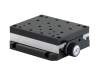
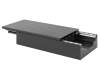
Stepper Motor Stages
Stepper motors are often used in open-loop control systems, a lower cost alternative to closed-loop DC servo systems. They operate using the basic principle of magnetic attraction and repulsion. Steppers convert digital pulses into mechanical shaft rotation. The amount of rotation is directly proportional to the number of input pulses generated, and speed is proportional to pulse frequency. Pulse count is a good indicator of position, and adding a shaft encoder can further improve performance.
| Series | Travel Range (mm) |
Minimum Incremental Motion (µm) |
Bi-directional Repeatability, Guaranteed (µm) |
Accuracy, Guaranteed (µm) |
Maximum Speed (mm/s) |
Normal Load Capacity (Cz) (N) |
|---|---|---|---|---|---|---|
 MFA Miniature Steel Stepper Motor Linear Stages |
25 | 0.1 | ±0.75 | ±3 | 1 | 50 |
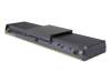
 UTS Low Profile Steel Stepper Motor Linear Stages |
50 100 150 |
0.33 | ±3 | ±2.5 ±3.5 ±4 |
PP: 20 PPV6: 10 |
PP: 200 PPV6: 100 |
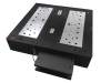
 MTN High Load Steel Stepper Motor Linear Stages |
100 200 300 |
0.1 | ±2.75 | ±2.5 ±2.5 ±3 |
PP: 40 PPV6: 20 |
1000 |
 ILS 50-250 mm Travel Aluminum Stepper Motor Linear Stages |
50 100 150 200 250 |
1 | ±1 | ±1.5 ±2 ±2.5 ±3.7 ±5 |
50 | 250 |
 IMS 300-600 mm Travel Aluminum Stepper Motor Linear Stages |
300 400 500 600 |
1.25 | ±1.25 | ±5 ±5 ±6 ±9 |
100 | 600 |
 CL Intelligent Stepper Linear Stage With Integrated Controller |
50 100 200 |
0.15 | ±2.25 ±2.5 ±2.5 |
±2 ±2.5 ±4 |
20 | 250 |
30.3 µm with XPS; 0.5 µm with ESP302 or SMC100PP.
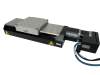
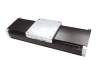
DC Motor Stages
DC motors are best characterized by their smooth motion and high speeds. They provide good efficiency and a high power/weight ratio. A brushed DC motor essentially consists of a rotor placed in a magnetic field, which causes rotation when current is applied to the motor windings. The rotational speed is proportional to the applied voltage, while the torque is proportional to the current. Precise closed-loop servo positioning and speed control is typically achieved with a shaft-mounted rotary encoder, and for ultra-precise positioning, a direct reading encoder on the drive train may be used. Note that unlike stepper motors, DC motors do not provide full torque when idle.
| Series | Travel Range (mm) |
Minimum Incremental Motion (µm) |
Bi-directional Repeatability, Guaranteed (µm) |
Accuracy, Guaranteed (µm) |
Maximum Speed (mm/s) |
Normal Load Capacity (Cz) (N) |
|---|---|---|---|---|---|---|
 VP Compact Aluminum DC Motor Linear Stages |
25 | XL: 0.01 XA: 0.1 |
XL: ±0.07 XA: ±0.1 |
±1 | 25 | 60 |
MFA Miniature Steel DC Motor Linear Stages |
25 | 0.1 | CC: ±0.75 CCV6: ±1 |
±3 | CC: 2.5 CCV6: 1.25 |
CC: 50 CCV6: 25 |
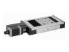
 UTS Low Profile Steel DC Motor Linear Stagess |
50 100 150 |
0.3 | ±1.75 | ±2.25 ±2.75 ±3.25 |
40 | 200 |
 GTS High Accuracy Aluminum DC Motor Linear Stages |
70 150 |
0.1 | ±0.1 | ±1 | 50 | 100 |
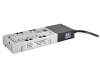
 MTN High Load Capacity Steel DC Motor Linear Stages |
100 200 300 |
0.6 | ±1.5 | ±2.5 ±2.5 ±3 |
100 | 1000 |
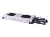
ILS 50-250 mm Travel Aluminum DC Motor Linear Stages |
50 100 150 200 250 |
HA: 0.3 CC & CCL: 1 |
HA: ±0.35 CC & CCL: ±1 |
HA / CC & CCL: ±1.25 / ±1.5 ±1.5 / ±2 ±2 / ±2.5 ±3 / ±3.75 ±3.75 / ±5 |
HA & CC: 100 CCL: 50 |
250 |
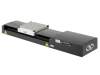
IMS 300-600 mm Travel Aluminum DC Motor Linear Stages |
300 400 500 600 |
CCHA: 0.2 CC: 1.25 |
CCHA: ±0.5 CC: ±1.25 |
CCHA / CC: ±4 / ±5 ±4 / ±5 ±5 / ±6 ±6.5 / ±9 |
200 | 600 |
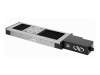
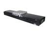
Brushless DC Motor Stages
Compared to brushed DC motor of the same size, brushless DC motor provides higher torque, faster speed and finer repeatability. The BLDC stages are ideal for applications that require low maintenance and exceptional reliability.
| Series | Travel Range (mm) |
Minimum Incremental Motion (µm) |
Bi-directional Repeatability, Guaranteed (µm) |
Accuracy, Guaranteed (µm) |
Maximum Speed (mm/s) |
Normal Load Capacity (Cz) (N) |
|---|---|---|---|---|---|---|
 MTN High Load Steel BLDC Motor Linear Stages |
100 200 300 |
0.3 | ±0.5 | ±4 ±4 ±4 |
250 | 1000 |
 IDL-BL Industrial BLDC Motor Linear Stages |
150 300 |
1 | ±1 | ±3 ±5 |
300 | 450 |
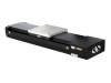
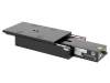
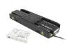
Linear Motor Stages
Linear motors consist of a permanent magnet assembly which establishes a magnetic flux, and a coil assembly which generates a force proportional to coil current. Linear motors have become very important components of precision positioning systems, with numerous advantages over traditional mechanical actuators such as ball screws. These systems typically provide higher quality, frictionless motion, and higher speeds and acceleration.
| Series | Travel Range (mm) |
Minimum Incremental Motion (µm) |
Bi-directional Repeatability, Guaranteed (µm) |
Accuracy, Guaranteed (µm) |
Maximum Speed (mm/s) |
Normal Load Capacity (Cz) (N) |
|---|---|---|---|---|---|---|
 XM Ultra-Precision Linear Motor Stages |
XMS: 50 100 160 XML: 210 350 |
0.0011 | ±0.04 | XMS: ±0.75 XML: ±1.5 |
300 | XMS: 100 XML: 300 |
 IMS-LM 600 N Load Aluminum Linear Motor Stages |
300 400 500 600 800 1000 1200 |
0.02 | 300-600 mm: ±0.25 800-1200 mm: ±0.5 |
±4.5 ±4.5 ±5.5 ±7.5 ±9 ±9 ±9 |
10002 | 600 (SA: 100) |
 IILS-LM 250 N Load Aluminum Linear Motor Stages |
100 200 300 |
0.01 | ±0.3 | ±1.5 ±2 ±2.5 |
500 | 250 |
 DL Optical Delay Line Linear Motor Linear Stages |
125 225 325 |
0.075 | ±0.15 | ±1.5 ±2 ±2.5 |
500 | 20 |
 ONE-XY Series Mid-Travel Integrated XY Linear Stages |
50 90 190 290 |
0.05 | ±0.07 ±0.08 ±0.09 ±0.1 |
N-HA / HA: ±1.5 / ±0.3 ±2 / ±0.3 ±2.5 / ±0.4 ±3 / ±0.5 |
200 | 100 120 150 350 |
 IDL Industrial Grade Linear Motor Linear Stages |
100 200 300 400 450 500 600 700 750 1000 1200 |
0.05 | 100-600 mm: ±0.25 700-1200 mm: ±0.5 |
±2 ±2 ±2 ±2.3 ±2.5 ±2.7 ±3 ±3.3 ±3.5 ±4.3 ±5 |
2000 | IDL165: 450 IDL225: 1000 IDL280: 1500 IDL560: 2000 |
1When driven with an XPS-DRV11 universal driver card and dependent on environment, load and speed conditions.
2With XPS-EDBL high-power motor driver. Maximum speed is 500 mm/s with XPS-DRV11 universal driver card.