DynamYX® RS Reticle Positioning Air Bearing Stage
DynamYX® RS Reticle Positioning Air Bearing Stage
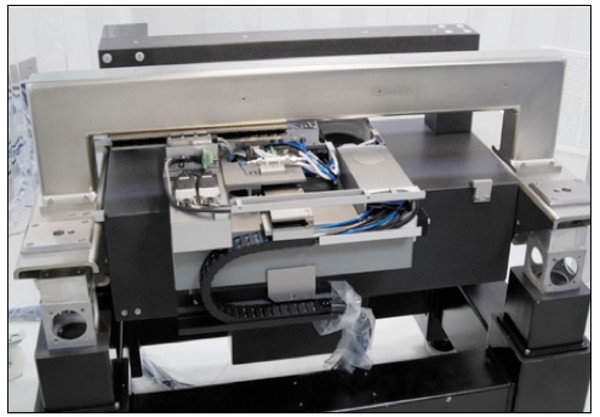
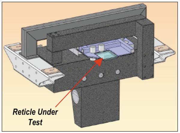
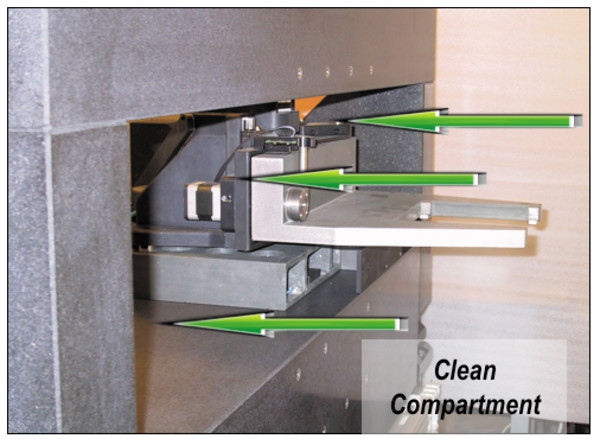
The DynamYX® RS Reticle Positioning Stage is designed for reticle inspection and repair applications. It features an extremely rigid ceramic reticle holder that is mounted to a single plane air bearing carriage. The cantilevered substrate is located away from all moving elements of the stage, which ensures the cleanest possible environment.
- Ideal for reticle inspection and repair applications
- Acceleration: 0.25G X and Y Axes
- Velocity: 250mm/sec
- Repeatability: ±25nm
- Accuracy: 0.5µm
- Travel Range: 290mm by 155mm See All Features
| Compare | Description | Drawings, CAD & Specs | Avail. | Price | ||
|---|---|---|---|---|---|---|
 | DYNAMYX-RSAir Bearing Stage, Reticle Positioning, DynamYX® RS |
Specifications
- BearingsVacuum/pressure air bearing
- Drive TypeIronless linear motor
- Maximum Speed400 mm/s
- Weight550 kg
Features
Newport Air Bearing Stage Solutions
Newport's reputation for being the premier supplier of high-precision motorized staes is exemplified by our full line of Air Bearing Positioning Systems. Additionaly, our dedicated OEM group has the knowledge and expertise needed to address the most complex and demanding motion control applications. This video provides an overview of the DynamYX, HybrYX and SinguLYS air bearing stage solutions.
DynamYX Family of Air-bearing Stages
Full Open Aperture Design
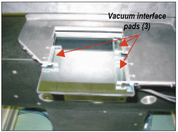
Chuck Interface
Linear Motor Drives
Position Feedback
The positioning loop on DynamYX may be closed using a single linear encoder for each axis. As shown in the adjacent illustration, the encoder measuring positions are closely located to the substrate’s surface reducing the already minimal abbe offset affect. For the X-axis, the linear scale is typically mounted to the underside of the bridge structure with the read-head in-line with the system’s optical path and affixed to the moving ceramic guide. System architectures that do not allow this configuration can be accommodated by mounting the X-axis scale to a supplementary SiC spar located at the rear side of the system. The Y-axis has its scale mounted to a small SiC bracket on the moving carriage. The read head is fixed to the arm of the L-shape structure. Read-heads which have fixed positions relative to the tool’s optical path are beneficial in optimizing precision. With an encoder signal period of 2mm, resolutions down to 0.1nm are possible with Newport’s XPS or SPS controllers each with internal 20,000 times interpolation. Equipped with linear encoders the DynamYX is an extremely accurate and very repeatable platform allowing for very high accuracy through error mapping. The geometric stability of the ceramic elements of these stages results in systems that can be mapped once at our factory then, upon installation, only require a simple length calibration to compensate for uniform thermal expansion. For applications where the accuracy requirements exceed the capabilities of error compensation, or in certain scanning modes where the absolute position of the stage must be the basis of a very precise trigger or latch, linear encoders must yield to laser interferometers which are also part of our offering.
Stiff and Stable Design
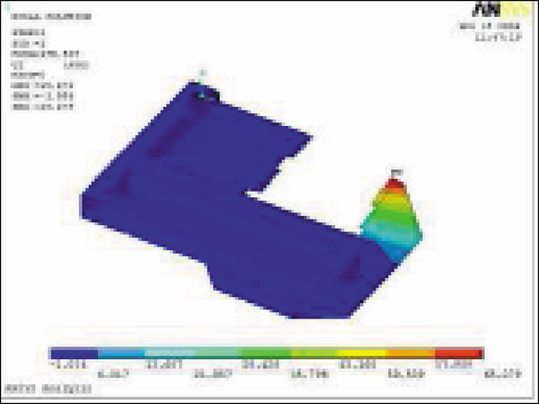
FEA of the cantilevered Silicon Carbide reticle holder was used to secure stiffness and stability of the design. The RS reticle holder has a higher natural frequency in the vertical axis than the substrate is supports.