Optical Mirror Mount Technology Guide
An Optical Mirror Mount is a device used in optics research that securely holds a mirror in place while allowing for precision tip and tilt adjustment. Due to the sensitive nature of optics research, optical mirror mounts are typically mounted to an optical table to provide a high level of vibration isolation. Mirror mounts can be adjusted by hand with a micrometer head or adjustment screw, and can be motorized for automation by using a motorized actuator. Adjustment mechanisms include Kinematic, Gimbal, and Flexure.
Mirror Mount Adjustment Mechanisms
Kinematic Mirror Mounts
Kinematic mirror mounts are, by far, the most common type, owing to excellent stability and relatively low cost. The kinematic mechanism is the best option for providing the required performance for the vast majority of experiments performed in labs today. It does, however, have drawbacks: cross-coupled adjustment, beam translation and limited angular travel. The location and orientation of the axes of rotation are usually behind the optic and non-stationary. This causes the axes move with every adjustment such that they do not stay orthogonal to the optical axis, so cross-coupled motion occurs during adjustment. Secondly, since the axes of rotation are behind the optic when adjustments are made, both rotation and translation of the optic occur. Finally, the angular travel range of most kinematic mounts does not exceed ±10° due to the physical limitation of the springs and adjustment screws used. The limitations in the kinematic mount incentivized the creation of the gimbal mechanism which overcame these problems.
Any optical mirror mount’s position can be defined uniquely in terms of six independent coordinates - three translations and three rotations, with respect to some arbitrary fixed coordinate system. A mirror mount is said to be kinematic when the number of degrees of freedom (axes of free motion) and the number of physical constraints applied to the mount total six. This is equivalent to saying that any physical constraints applied are independent (non-redundant). A kinematic optical mount, therefore, has six independent constraints.
The most common type of kinematic mount is the cone, groove, and flat mount schematically illustrated in the below figure. Consider the optic as being attached to the coordinate system of the three spheres in the figure and its corresponding mount having the cone, vee, and flat. If the optic is first seated in the cone, three degrees of freedom (x, y, and z translations) are eliminated without redundancy.
At this point, the optic can still rotate freely about all axes. Next, the second sphere is seated in the groove, which is aligned towards the cone. This constrains or eliminates two more degrees of freedom, pitch and yaw, as shown in the Figure. The alignment of the groove towards the cone is important in order not to over-constrain one or more of the translation degrees of freedom. Finally, there is only one degree of freedom left to constrain, roll about the x-axis. This is accomplished by seating the third sphere on the flat. Six non-redundant constraints make this a kinematic mount.
The advantages of a kinematic mount are: increased stability, distortion free optical mounting and, in the case of a kinematic base, removable and repeatable re-positioning. It is easy to imagine with the mount of Figure 1, that the plate containing the cone, vee, and flat could thermally expand at a different rate than the optic without introducing any distorting load to the optic. The mount would simply expand about the ball and cone. The second and third balls would both slide on the groove and flat, respectively. If, on the other hand, the mount was non-kinematic (for example, if the groove were rotated 90° about z), as the plate expanded or contracted along the x direction, it would tend to warp the optic since the second ball could no longer slide in the groove.
To hold a super flat mirror in a mount, care must be taken to avoid over-torquing the screws, which would distort the surface, ruining the surface flatness. It is important to use hinge clips on low distortion mounts and tighten very gently. An excellent choice to use with super flat mirrors is Newport’s Suprema ZeroDrift Thermally Compensated Mirror Mounts. ZeroDrift technology has been combined with a low wavefront distortion (LWD) retainer to hold mirrors in a way that will not induce optical distortion. It uses an axial three-point mounting method to gently, but securely, hold optics with tight flatness tolerances. These mounts also contain kinematic elements that compensate for temperature-induced alignment drift, resulting in an 85% improvement in optical pointing stability, when compared to other stainless steel mounts.
Gimbal Mounts
It is common to make kinematic mounts adjustable, by attaching a screw drive to the second and third spheres (Figure 1) to provide angular adjustment of the optic with respect to the base. This is the basis of design for Newport’s Kinematic Mirror Mounts. One drawback to this type of mount is the location and orientation of the axes of rotation of the mount. They are usually behind the optic and non-stationary. That is to say that the axes move with every adjustment. This introduces two problems that must be overcome. First, since the axes move, they do not stay orthogonal to the optical axis, so cross-coupled motion occurs during adjustment. Rotation purely in one of the directions orthogonal to the optical axis requires adjusting both axes of the kinematic mount. Secondly, since the axes of rotation are behind the optic when adjustments are made, both rotation and translation of the optic occur. Use of a gimbal mount eliminates both of these problems.
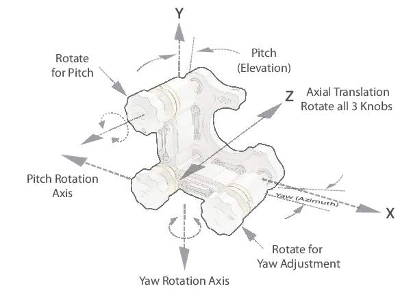
A gimbal mechanism has axes of rotation, which are orthogonal and fixed in space. The rotation axes are made to intersect at the center of the front surface of the optic in the mount, which not only allows for non-coupled rotation adjustment of the optic, it also eliminates beam translation, as shown in Figure 2. Gimbal mounts also have travel ranges that are significantly larger than their kinematic counterparts. Since the rotation is typically guided by an axel, many gimbal designs have a full 360 degrees of angular travel in both axes. Mounts using the gimbal mechanism, however, tend to be larger and more expensive. As a result, hybrid designs combining the best attributes of kinematic and gimbal mechanisms have emerged, which have the stability and lower cost of a kinematic design and avoid cross coupling and beam translation.
Flexure Mounts
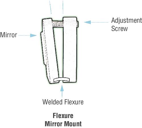
A flexure is a positioning mechanism, which uses the elastic deformation of a material to provide angular translation. Mounts that use a flexure mechanism benefit from compact size and resistance to shock owing to welded unibody construction. For this reason, flexure mounts are popular for incorporation into instrumentation and other such systems. The flexure mount has limited travel range, typically half that of a kinematic mount and is more susceptible alignment drift from temperature fluctuations.
Mirror Mount Drive Types
Allen-Key Drive
Mirror mounts with Allen-Key drives are used for “set-and-forget” applications where few or no follow-up adjustments are made. The lack of a knob helps to discourage unwanted tampering. Allen key adjusters can be adjusted in tight locations where a persons hand is too large to fit and can also be offered with typically lockable versions.
Knob Drive
Mirror mounts with Knob drives should be selected for applications where frequent adjustments will be made. Keep in mind that the diameter of a knob affects adjustment sensitivity. Larger diameter knobs, provide better sensitivity but also take up more space. We also offer Actuator Knobs that can be attached to an Allen-Key drive to make the mount knob adjustable.
Micrometer Head Drive
Mirror mounts with Micrometer Head drives should be selected for applications where exact position needs to be recorded and referenced. Although micrometers have position scales on their spindles, their thread pitch is only 51 TPI, half that of a standard adjustment screw limiting their sensitivity
Linear Actuator Drive
Mirror mounts with Motorized Linear Actuators can be used for automated positioning, and adjustments where reaching an Allen-key or knob may be difficult. You may also be able to make more precise adjustments when using a linear actuator with a motion controller.
Mirror Mounts Without the Drive Included
We offer optical mirror mounts with the drive not included, so you can add your own drive, change drives as required, or add one of our linear actuators to convert it to a motorized optical mount.
Mirror Mount Material Characteristics
Stiffness
Stiffness is a measure of the amount of stress (force/area) required to cause a given amount of strain (normalized deformation). Stress and strain are proportional and related by the equation σ = Eε, where σ and ε are stress and strain respectively, and E is Young’s Modulus, which is material dependent. A material is stiffer for larger values of E and more compliant for smaller values. For example, stainless steel is approximately three times stiffer than that of aluminum (see table). Aluminum, on the other hand, is 1.3 times more compliant than brass. Specific stiffness (Young’s Modulus divided by the material density) is important when settling time or vibration immunity is an issue. Components with the same shape and specific stiffness will have the same fundamental resonant frequencies. Higher specific stiffness results in higher resonant frequencies, faster settling times, and a reduction in vibration disturbances.
Thermal Expansion
Temperature changes cause size and shape changes in a mounting component. The amount of size and shape change is dependent on the size of the component, the amount of temperature change, and the material used. The equation relating dimensional change to temperature change is ΔL = αLΔT where α is the material dependent coefficient of thermal expansion. The thermal expansion of stainless steel is roughly half that of aluminum. This can be important when the mounting component is being used in an application requiring interferometric stability. Note that aluminum is the best choice when temperature change across the component is non-uniform. The thermal conductivity of aluminum is ten times greater than that of stainless steel, so heat can be dissipated more readily, thus reducing the magnitude of the thermal gradients and distortion. The distortion caused by non-uniform temperature changes is proportional to the coefficient of thermal expansion divided by the coefficient of thermal conductivity. Thus, aluminum distorts on the order of three times less than stainless steel in a non-uniform temperature environment.
| Material Properties | Aluminum | Stainless Steel |
|---|---|---|
| Stiffness, k (MPSI) | 10.5 | 28 |
| Density, ρ (lb/in.3) | 0.097 | 0.277 |
| Specific Stiffness, k/ρ (M in.) | 108 | 101 |
| Coefficient of Thermal Expansion, α (µ in./in./°F) | 12.4 | 5.6 |
| Coefficient of Thermal Conduction, c (BTU/hr-ft-°F) | 104 | 15.6 |
| Relative Thermal Distortion (α/c) | 0.12 | 0.36 |
Material Instability
Material instability is the change of physical dimension with time: so-called cold flow or creep. For aluminum and stainless steel, the period of time required to see this creep may be on the order of months or years.
Usually, the mechanical design of the component contributes much more to the instability than does the choice of material. For example, the lubrication on the micrometer’s threads can begin to migrate over time, causing a slight shift in the micrometer.
Summary of Materials Evaluation
Each of the materials used in positioning components have their own unique set of advantages and disadvantages. Unfortunately, a universal material that meets all requirements does not exist. We summarize here the characteristics of the materials outlined in the chart.
Aluminum: Aluminum is a lightweight material, resistant to cold flow or creep, with good stiffness-to-weight ratio. It has a relatively high coefficient of thermal expansion, but it also has a high thermal conductivity, making it a good choice in applications where there will be thermal gradients or where rapid acclimatization to temperature changes is required. Aluminum is fast machining, cost effective, and widely used in component structures. Aluminum is non-rusting and generally corrosion-resistant in a laboratory environment, even when the surface is unprotected. It has an excellent finish when anodized. However, anodized surfaces are highly porous, making them unsuitable for use in high vacuum. Vacuum applications require the use of unfinished aluminum surfaces.
Stainless Steel: Steel has a high modulus of elasticity, giving it very good stiffness (nearly three times that of aluminum), and good material stability. It also has about half the thermal expansion of aluminum, making it an excellent choice in typical laboratory environments where there are uniform changes in temperature. Machining of steel is much slower than aluminum, making steel components considerably more expensive. Corrosion of steel is a serious problem. Stainless steel alloys avoid the corrosion problems of other steels. Stainless steel is well suited to high vacuum applications, but the design of the component must also incorporate other factors.
Exterior Finish
Anodized aluminum provides excellent corrosion resistance and a good finish. Black is the color most often used on optical mounts. The anodized surface is highly porous. For this reason, only unanodized aluminum is used in high vacuum applications. However, this porosity results in a matte surface that does not specularly reflect light, adding to its value in optical mounts. Anodizing hardens the surface; improving scratch and wear resistance.
Steel parts are generally plated or painted. Platings are often chrome, nickel, rhodium, or cadmium. A black oxide finish is often used on screws and mounting hardware to prevent rust. Painted components should be avoided. Paint will eventually flake off, contaminating the optics or the moving parts of the positioner.
Stainless steel alloys avoid the rust problems of other steels. They are very clean materials that do not require special surface protection. A glass-bead blasted surface will have a dull finish that does not specularly reflect.
Vacuum Compatibility
Many optical mirror mounts can be vacuum prepared. Please look for the “Vacuum Compatible” statement on the specific product page. “Vacuum Compatible” products are prepared for 10-6Torr. If you require products specially prepared for 10-3Torr, or greater than 10-6Torr environments, please contact our technical staff for a quotation.
Vacuum Preparation
Preparation for vacuum environments depends on the vacuum you wish to maintain. The word “vacuum” does not adequately specify the conditions for a specific application. Acceptable levels of outgassing, mass loss and volatile condensable materials can vary with the application, pumping capacity, temperature, etc. It is, therefore, essential that the specific requirements be reviewed and understood prior to placing any component in a vacuum environment.
10-3 Torr environments: In general terms, a vacuum of 10-3 Torr requires minimal change to many of our products with the exception of possible lubricants. In this environment, it is not uncommon to use anodized parts. Limited use of plastics should not pose any problems.
10-6 Torr environments: Components used in a vacuum of 10-6 Torr are specifically prepared for this environment. Many of the materials used in standard components will outgas in a high vacuum, resulting in a “virtual” leak, which limits the ability to maintain a high vacuum. Highly porous anodized aluminum surfaces can trap large amounts of air molecules, resulting in significant outgassing. For those components, within this catalog, specified as “Vacuum Compatible” we perform the following in preparation:
Products with anodized aluminum are created without anodize. As such, we only use unanodized aluminum, stainless steel or equivalent materials. Plastic knobs and handles are either removed or replaced (at additional cost) with high vacuum materials such as steel or Delrin. In some cases, you may choose to maintain the plastic knob to avoid the incremental costs associated with producing an alternative design. In spite of plastics permeability it is common to use plastics in vacuum systems because of their insulating properties and price. Holes not tapped through are vented; or special vented hardware is used. Hardware and lubricants are changed to special vacuum compatible materials. Finished units are completely cleaned and sealed in appropriate packaging material. Additional vacuum preparation steps, or preparation for vacuums of greater than 10-6, require special handling, including baking the product in a vacuum. If you have requirements at this level, please contact our technical staff to discuss the options available.