Optical Mirror Selection Guide
Overview
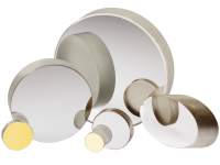
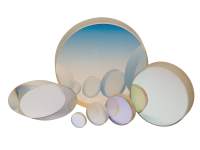
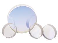
Mirrors are probably the most commonly used optical elements in your lab, and their quality, performance, and reliability are key to the success of your experiment. That's why we provide a variety of mirrors so you can be assured to find what you need. When choosing an Optical Mirror, keep in mind the reflectivity, laser damage resistance, and coating durability. For quick delivery, all our mirrors are shipped from stock.
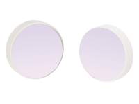
Metallic Coatings
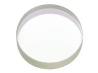
Broadband metallic coated mirrors are good general-purpose mirrors because they can be used over a very broad spectral range from 450 nm to 12 µm. They are also insensitive to polarization and angle of incidence, and provide a constant phase shift, making them appropriate for ultrashort-pulse applications. Their softer coating, however, makes them more susceptible to damage, and special care must be taken when cleaning.
Dielectric Coatings
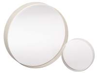
Dielectric mirrors offer higher reflectivity over a broad spectral range of a few 100 nm. Their coating is more durable, making them easier to clean, and more resistant to laser damage. We offer broadband dielectric mirrors that are ideal for general laboratory use as well as mirrors especially for high-power Nd:YAG applications at 1.064 µm and 532 nm and DUV and UV applications.
Ultrafast Coatings
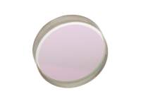
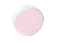
Standard dielectric mirror coatings can cause significant dispersive effects for ultrashort pulses, such as those produced by Ti:Sapphire lasers. The dispersion of the material and the interference effects between coating layers result in phase variations at specific wavelengths. Since the group delay is related to the slope of the phase variation, these wavelength regions introduce significant GDD errors that can broaden and distort your pulse. Therefore, for applications that require steering ultrashort pulses, we suggest to use ultrafast mirrors.
Selecting an Optical Mirror
See Optical Mirrors to shop or browse all of our standard models, or select a product family below for more information. We also offer a wide variety of Mirror Mounts.
| Broadband Metallic Mirror Families | Reflective Coatings | Diameters | Material | |
 |
Broadband Metallic Mirrors | AL.2 (250-600 nm) ER.1 (450-700 nm) ER.2 (480-20,000 nm) ER.4 (650-20,000 nm) |
0.5 to 8.0 in. (Square, Elliptical D-shaped, Concave available) |
Borofloat® 33 or Zerodur® |
 |
Utility Broadband Metallic Mirrors | ER.3 (400-10,000 nm) | 1.0 & 2.0 in. (Square available) |
Float Glass |
 |
PinholeFree Broadband Metallic Mirrors | AL.2-PF (250-600 nm) ER.1-PF (450-700 nm) ER.2-PF (480-20,000 nm) |
0.5, 1.0 & 2.0 in. | Borofloat® 33 |
| Broadband Dielectric Mirror Families | Reflective Coatings | Diameters | Material | |
 |
Broadband Dielectric Mirrors | BD.1 (488-694 nm) BD.2 (700-950 nm) |
0.5 to 8.0 in. (Square, Elliptical, D-shaped available) |
Borofloat® 33 or Zerodur® |
 |
Ultra-broadband Dielectric Mirrors | BB.1 (350-700 nm) BB.2 (610-1130 nm) BB.3 (350-1100 nm) |
1.0 in. | UV Grade Fused Silica |
 |
BroadBeam High Reflector Mirrors | BB.HR2 (350-1100 nm) | 1.0 in. | UV Grade Fused Silica |
 |
High Performance SuperMirrors | SB.1 (485-700 nm) SR.30F (583-663 nm) SR.40F (761-867 nm) SR.50F (996-1134 nm) SR.60F (1241-1412 nm) SR.70F (1457-1659 nm) |
1.0 in. (Concave available) |
UV Grade Fused Silica |
| Laser Line Dielectric Mirror Families | Reflective Coatings | Diameters | Material | |
 |
Laser Line Dielectric Mirrors | RM.2 (325 nm) DM.6 (441.6 nm) DM.5 (488-514.5 nm) DM.11 (532 nm) DM.4 (632.8 nm) DM.10 (1030-1090 nm) DM.8 (1520-1580 nm) |
0.5 to 8.0 in. (Elliptical available) |
Borofloat® 33 or Zerodur® |
 |
High-Energy Nd:YAG Laser Mirrors | HM.70/HM.75 (266 nm) HM.40/HM.45 (354.7 nm) HE.2/HM.30/HM.35 (532 nm) HE.1/HM.10/HM.15 (1064 nm) HDM.10/HDM.15 (532 & 1064 nm) |
1.0 & 2.0 in. | UV Grade Fused Silica |
 |
High Energy Excimer Laser Mirrors | EM.10/EM.15 (248 nm) EM.20/EM.25 (308 nm) EM.30/EM.35 (351-353 nm) |
1.0 & 2.0 in. | UV Grade Fused Silica |
 |
Ytterbium Doped Laser Mirrors | UF.F55 (505-530 nm) UF.F15 (1020-1050 nm) UF.DF55 (505-530 & 1020-1050 nm) |
1.0 in. | UV Grade Fused Silica |
| Ultrafast Mirror Families | Reflective Coatings | Diameters | Material | |
 |
FemtoOptics™ Femtosecond Optimized Silver Mirrors | EAG.1 (600-1000 nm) EAG.2 (470-1000 nm) |
1.0 & 2.0 in. (Concave available) |
N-BK7 |
 |
Ultrafast Mirrors with Low Group Delay Dispersion | UF.25 (700-930 nm) | 0.5, 1.0 & 2.0 in. (Concave available) |
N-BK7 |
 |
High Reflecting Pump Mirrors for Ultrashort Pulses | UF.20 (710-890 nm) | 0.5 & 1.0 in. (Concave available) |
N-BK7 |
 |
FemtoOptics™ High Reflector Harmonic Mirrors | UF.HR20/UF.HR25 (267 nm) UF.HR40/UF.HR45 (400 nm) |
1.0 in. | N-BK7 |
 |
Broadband Turning Mirrors for Ultrashort Pulses | UF.35P/UF.35S (680-1060 nm) | 1.0 & 2.0 in. | Fused Silica |
|
Super Broadband Ultrafast Turning Mirrors | UF.55P/UF.55S (670-1340 nm) | 1.0 in. | Fused Silica |
 |
Chirped Mirrors for Ultrashort Pulses | UF.40 (700-900 nm) | 1.0 in. | Fused Silica |
 |
FemtoOptics™ Chirped Mirrors Matched Pair | UF.42PAIR (700-890 nm) | 1.0 in. | Fused Silica |
| Parabolic Mirror Families | Reflective Coatings | Diameters | Material | |
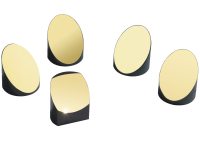 |
Off-Axis Replicated Parabolic Mirrors | Al (190-2000 nm) Au (800-15,000 nm) |
1.5 in. | Aluminum |
| Retroreflector Families | Reflective Coatings | Diameters | Material | |
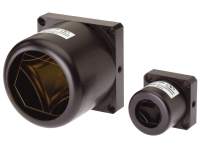 |
Broadband Hollow Retroreflectors | UV Al (225-700 nm) Al (400-700 nm) Ag (450-10,000 nm) Au (650-16,000 nm) |
1.0 & 2.5 in. | Borofloat® 33 |
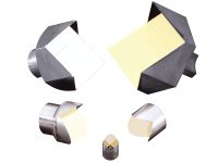 |
Replicated Hollow Metal Retroreflectors | Au (800-15,000 nm) | 0.5, 0.75, 1.0, 1.5 & 2.5 in. | Aluminum |
 |
Solid Glass Retroreflectors | Uncoated | 0.25, 0.5, & 1.0 in. | N-BK7 |
Broadband Metallic Coatings
| Coating Code | Wavelength Range (nm) | Reflectance | Damage Threshold (typical) | Features | |
|---|---|---|---|---|---|
 |
AL.2 (UV Al) |
250-600 | Ravg >90% | 100 W/cm2 CW 2 J/cm2 @ 355nm, 10ns, 20Hz |
UV Reflectivity enhanced by a MgF2 overcoat |
 |
ER.1 (Al) |
450-700 | Ravg >93% | 100 W/cm2 CW 0.5 J/cm2 @ 532nm, 10ns, 20Hz |
Visible and NIR reflectivity enhanced by a multilayer dielectric overcoat |
 |
ER.2 (Ag) |
480-20,000 | Ravg >96% @ 480-1100 Ravg >98.5% @ 1100-20,000 |
1000 W/cm2 CW 1 J/cm2 @ 1064nm, 10ns, 20Hz |
Visible and IR performance superior to aluminum coatings |
 |
ER.3 (Al) |
400-10000 | Ravg >90% @ 400-2000 | 100 W/cm2 CW 0.5 J/cm2 @ 10ns |
Economic broadband reflectors |
 |
ER.4 (Au) |
650-20,000 | Ravg >96% @ 650-1700 Ravg >98% @ 1700-20,000 |
200 W/cm2 CW 0.5 J/cm2 @ 1064nm, 10ns, 20Hz |
NIR to Infrared performance slightly higher than protected silver |
Broadband Dielectric Coatings
| Coating Code | Wavelength Range (nm) | Reflectance | Damage Threshold (typical) | Features | |
|---|---|---|---|---|---|
 |
BD.1 | 488-694 | RS, avg >99% RP, avg >98% |
500 W/cm2 CW 3 J/cm2 @ 532nm, 10ns, 10Hz |
Very high reflectivity over a broad wavelength range |
 |
BD.2 | 700-950 | RS, avg >99% RP, avg >97% |
1000 W/cm2 CW 4 J/cm2 @ 800nm, 10ns, 10Hz |
Very high reflectivity over a broad wavelength range |
 |
BB.1 | 350-700 | RS, avg, RP, avg >99% | 1 J/cm2 @ 355&532nm, 20ns, 20Hz | Special coating design to withstand higher damage threshold |
 |
BB.2 | 610-1130 | RS, avg, RP, avg >99% | 2 J/cm2 @ 1064nm, 20ns, 20Hz | Special coating design to withstand higher damage threshold |
 |
BB.3 | 350-1100 | RS, avg, RP, avg >99% | 5 J/cm2 @ 1064nm, 20ns, 20Hz | Special coating design to withstand higher damage threshold |
 |
BB.HR2 | 350-1100 | Ravg >97.5% | 1.3 J/cm2 @ 355nm 2.0 J/cm2 @ 532nm 2.3 J/cm2 @ 1064nm |
Great value for high reflectivity over an extremely wide wavelength range from UV to NIR |
 |
SB.1 | 485-700 | RS, avg, RP, avg >99.9% | 1000 W/cm2 CW 0.5 J/cm2 @ 485-700nm, 10ns |
Highest reflectivity broadband mirror commercially available |
 |
SR.xxF | 583-663 761-867 996-1134 1241-1412 1457-1659 |
RS, avg, RP, avg >99.97% | Highest reflectivity broadband mirror commercially available |
Laser Line Dielectric Coatings
| Coating Code | Wavelength Range (nm) | Reflectance | Damage Threshold (typical) | Features | |
|---|---|---|---|---|---|
 |
RM.2 | 325 | RS, RP >99% | 500 W/cm2 CW 0.5 J/cm2 @ 10ns |
Very high reflectivity, designed for use with 325 nm HeCd laser at 0-45° AOI |
 |
DM.6 | 441.6 | RS, RP >99% | 500 W/cm2 CW 1 J/cm2 @ 10ns |
Very high reflectivity, designed for use with 441.6 nm HeCd laser at 0-45° AOI |
 |
DM.5 | 488-514.5 | RS, RP >99% | 500 W/cm2 CW 1 J/cm2 @ 10ns |
Very high reflectivity, designed for use with 488 nm and 514.5 nm Argon-Ion laser at 0-45° AOI |
 |
DM.11 | 532 | RS, RP >99% | 500 W/cm2 CW 2 J/cm2 @ 10ns |
Very high reflectivity, designed for use with 532 nm Nd:YAG laser at 0-45° AOI |
 |
DM.4 | 632.8 | RS, RP >99% | 500 W/cm2 CW 5 J/cm2 @ 10ns |
Very high reflectivity, designed for use with 632.8 nm HeNe laser at 0-45° AOI |
 |
DM.10 | 1030-1090 | RS, RP >99% | 500 W/cm2 CW 4 J/cm2 @ 10ns |
Very high reflectivity, designed for use with 1064 nm Nd:YAG laser at 0-45° AOI |
 |
DM.8 | 1520-1580 | RS, RP >99% | 500 W/cm2 CW 10 J/cm2 @ 10ns |
Very high reflectivity, designed for use with 1550 nm Diode Laser laser at 0-45° AOI |
 |
HM.70 HM.40 HM.30 HM.10 |
266 354.7 532 1064 |
Ravg >99% |
CW Pulsed 3 KW/cm2 2.0 J/cm2 3 KW/cm2 3.5 J/cm2 3 KW/cm2 10 J/cm2 3 KW/cm2 45 J/cm2 |
Very high reflectivity, withstands high-energy Nd:YAG laser from at 0° AOI |
 |
HM.75 HM.45 HM.35 HM.15 |
266 354.7 532 1064 |
RS >99.7% RP >99% |
CW Pulsed 3 KW/cm2 2.0 J/cm2 3 KW/cm2 3.5 J/cm2 3 KW/cm2 10 J/cm2 3 KW/cm2 45 J/cm2 |
Very high reflectivity, withstands high-energy harmonic Nd:YAG laser pulses at 45° AOI |
 |
HE.1 | 1064 | RS, RP >99% | 3 KW/cm2 CW 40 J/cm2 @ 10ns, 20Hz |
Very high reflectivity, withstands high-energy 1064 nm Nd:YAG laser pulses at 45° AOI |
 |
HE.2 | 532 | RS, RP >99% | 3 KW/cm2 CW 10 J/cm2 @ 20ns, 20Hz |
Very high reflectivity, withstands high-energy 532 nm Nd:YAG laser pulses at 45° AOI |
 |
HDM.10 | 532 & 1064 | Ravg >99% | 3 KW/cm2 CW 8 J/cm2 @ 20ns, 20Hz |
Very high reflectivity, withstands high-energy 532 & 1064 nm Nd:YAG laser pulses at 0° AOI |
 |
HDM.15 | 532 & 1064 | RS >99.7% RP >99% |
3 KW/cm2 CW 8 J/cm2 @ 20ns, 20Hz |
Very high reflectivity, withstands high-energy 532 & 1064 nm Nd:YAG laser pulses at 45° AOI |
 |
EM.10 EM.20 EM.30 |
248 308 351-353 |
Ravg >99% | 3 KW/cm2 CW 500 mJ/cm2 @ 10ns, 10Hz |
Withstands high-energy 248nm KrF, 308nm XeCl or 351-353nm XeF laser pulses at 0° AOI |
 |
EM.15 EM.25 EM.35 |
248 308 351-353 |
RS, RP >99% | 3 KW/cm2 CW 500 mJ/cm2 @ 10ns, 10Hz |
Withstands high-energy 248nm KrF, 308nm XeCl or 351-353nm XeF laser pulses at 45° AOI |
 |
UF.F15 | 1020-1050 | RS, RP >99.5% | 10 J/cm2 @ 1064nm, 10ns, 10Hz | Very high reflectivity, withstands high-energy 1020-1050 nm Ytterbium laser pulses at 45° AOI |
 |
UF.F55 | 505-530 | RS, RP >99.5% | 2 J/cm2 @ 532nm, 10ns, 10Hz | Very high reflectivity, withstands high-energy 505-530 nm Ytterbium laser pulses at 45° AOI |
 |
UF.DF55 | 505-530 & 1020-1050 | R >99.5% | Very high reflectivity, designed for 505-530 & 1020-1050 nm Ytterbium laser pulses at 45° AOI |
Ultrafast Coatings
Substrate Materials
Borofloat® is a borosilicate glass with a low coefficient of thermal expansion. It is mainly used for non-transmissive optics, such as mirrors, due to its low homogeneity and high bubble content.
Zerodur® is a glass ceramic material that has a coefficient of thermal expansion approaching zero, as well as excellent homogeneity of this coefficient throughout the entire piece. This makes Zerodur ideal for mirror substrates where extreme thermal stability is required.
Fused Silica is synthetic amorphous silicon dioxide of extremely high purity. This non-crystalline, colorless silica glass combines a very low thermal expansion coefficient with good optical qualities, ideal for use with high-energy lasers due to its high energy damage threshold.
Please see Optical Materials for more information.
| Material | Coefficient of Thermal Expansion |
Cost | Features |
|---|---|---|---|
| Borofloat® | 3.25 x 10⁻⁶/°C | Low | Best all around mirror substrate, low expansion borosilicate glass, resistant to thermal shock |
| UV Fused Silica | 0.52 x 10⁻⁶/°C | High | Low thermal expansion for excellent stability, high laser damage resistance |
| Zerodur® | 0 ± 0.1 x 10⁻⁶/°C | Moderate | Nominally zero thermal expansion for ultra-high stability, unique glass-ceramic material |
Optical Surfaces
The surface quality of an optic is described by its surface figure and irregularity. Surface figure is defined as peak-to-valley deviation from flatness, including any curvature (also known as power) present. Surface irregularity is represented by the peak-to-valley deviations when power is subtracted. Our front-surface figure is typically guaranteed flat to less than λ/10 at 633 nm over the clear aperture. Our 2" mirrors have a typical figure of λ/4 over the clear aperture. When preservation of wavefront is critical, choose a flatness of λ/10 or better.
As for surface quality, the smaller the scratch-dig specification, the lower the scatter. Our metal mirrors offer a scratch-dig of 25-10; our dielectric mirrors, 15-5; and our UV mirrors, 10-5, which is ideal for the most demanding laser systems where low scatter is critical.
Dig: a defect on the surface of an optic as defined in average diameter in 1/100 of a millimeter.
Scratch: a defect on an optic that is many times longer than it is wide.
Selecting the proper mirror for your application requires making a number of choices. A few of the many considerations include: reflectivity, laser damage resistance, coating durability, thermal expansion of the substrate, wavefront distortion, scattered light, and certainly cost. The following tables should help in comparing the available choices from Newport.
The mirror application drives the requirements for surface flatness and surface quality. When preservation of wavefront is critical, a λ/10 to λ/20 mirror should be selected; when wavefront is not as important as cost, a λ/2 to λ/5 mirror can be used. For surface quality, the tighter the scratch-dig specification, the lower the scatter. For demanding laser systems, 20-10 to 10-5 scratch-dig is best. For applications where low scatter is not as critical as cost, 40-20 to 60-40 scratch-dig can be used. Please see Optical Surfaces for more information.
Surface Flatness
| Figure | Cost | Applications |
|---|---|---|
| λ/2 | Low | Used where wavefront distortion is not as important as cost |
| λ/5 | Moderate | Excellent for most general laser and imaging applications where low wavefront performance must be balanced with cost |
| λ/10 | Moderate | For laser and imaging applications where low wavefront distortion, especially in systems with multiple elements |
| λ/20 | High | For the most demanding laser systems where maintaining accurate wavefront is critical to performance |
Surface Quality
| Scratch-Dig | Cost | Applications |
|---|---|---|
| 60-40 | Low | Used for low-power laser and imaging applications with unfocused beams where scatter is not critical |
| 40-20 | Moderate | Ideal for laser and imaging applications with collimated beams where scatter begins to affect system performance |
| 20-10 | High | Excellent for laser systems with focused beams that can tolerate little scattered light |
| 10-5 | High | For the most demanding laser systems where low scatter is critical to performance |
Optical Mirror Selection FAQ
Q: Is metallic or dielectric mirror better for use with polarized light?
A: It depends on the characteristics of the light (wavelength, type of polarization, etc.), the specific properties of the reflective coating, and the application (angle of incidence, polarization preservation requirement, etc.). In many cases, standard metallic mirrors more or less preserve polarization after reflection, and standard dielectric mirrors can also roughly preserve S or P linearly polarized light after reflection. However, standard dielectric mirrors are not typically recommended for circularly or elliptically polarized light. But as these general guidelines do not always apply for every application, Newport suggests trying a mirror with your application before sourcing a larger quantity of mirrors if preserving polarization is critical to your application.
Q: Newport offers several mirror substrates. What is best for my application?
A: Borofloat® 33 is a good substrate for most general purpose applications. It is a high quality borosilicate glass that offers low thermal expansion and high thermal shock resistance at a moderate cost. For applications requiring high thermal stability, Zerodur substrates are ideal. It is a glass ceramic material with a coefficient of thermal expansion approaching zero and excellent homogeneity throughout an entire piece of material. When high-energy damage thresholds are the primary concern, Fused Silica substrates should be considered. It is a synthetic, non-crystalline, colorless, amorphous silicon dioxide of extremely high purity. And for the lowest cost solution (with lower performance requirements), float glass substrates may be used. Please see Optical Materials for more information.
Q: I see visible scratches and pits in my mirror or lens, how will these imperfections affect light reflection or transmission?
A: These imperfections are specified by a scratch-dig designation, with the first number indicating the maximum width allowance for a scratch and the second number stating the maximum diameter for a dig in hundredths of a millimeter. The value indicating the scratch is an arbitrary number from 10 to 80, determined by visual comparison to standards defined in U.S. Military specification MIL-PRF-13830B - the lower the number, the less visible the scratches are, and vice versa. Scratches and digs will result in light being scattered, with lower scratch-dig specs causing less scatter.
For the most demanding laser systems, such as intra-cavity and moderate to high power lasers, 10-5 and 20-10 scratch-dig is recommended. For many general purpose and research applications which can tolerate little scattered light, 40-20 scratch-dig is suitable. And for less critical applications where cost is a priority over scattered light, or if a substantial amount of light is available, 60-40 scratch-dig can be used.
Q: For low light applications, what are the best optics specifications?
A: A successful low light application must preserve every photon possible. The first way to assist with this is to choose mirrors and lenses with low scratch-dig specifications - such as 20-10 and 10-5 - to reduce scattered (i.e., wasted) light. Next, select mirrors with high reflective coatings - Newport offers many standard dielectric mirrors with average reflectivity greater than 99%. Then, utilize lenses with high performing anti-reflection coatings to improve transmission efficiency - Newport offers several standard coatings with average reflectivity per surface of less than 0.5%, compared to typical reflectivity per surface of 4% for uncoated lenses.