Selection of Dispersing Systems

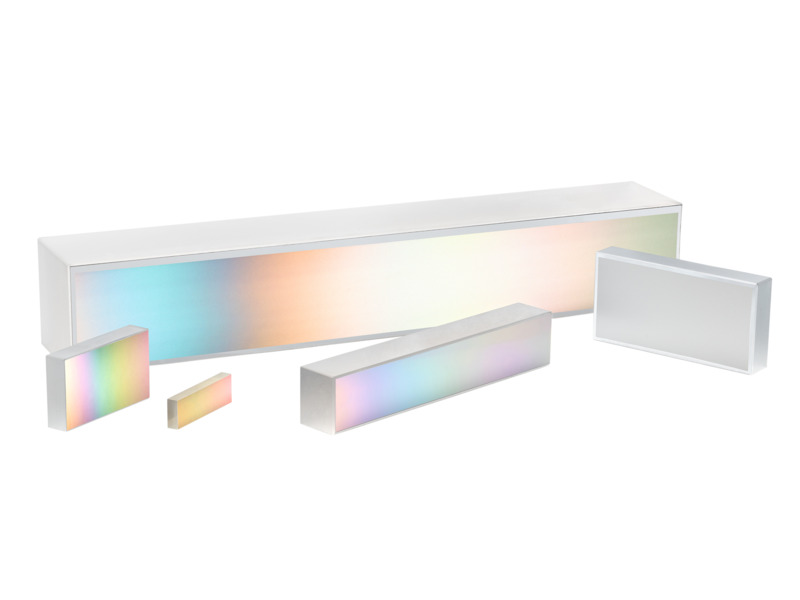
As a leader in the design and manufacture of diffraction gratings, Richardson Gratings offers precision components for analytical instruments, laser and telecommunications equipment manufacturers, and for researchers and astronomers. Our standard gratings offering includes Plane Ruled Reflection Gratings, Plane Holographic Reflection Gratings, Echelle Reflection Gratings, Plane Transmission Gratings, and Concave Constant-Deviation Monochromator Gratings.

Reflection Grating Systems

Reflection grating systems are much more common than transmission grating systems. Optical systems can be 'folded' with reflection gratings, which reflect as well as disperse, whereas transmission grating systems are 'in-line' and therefore usually of greater length. Moreover, reflection gratings are not limited by the transmission proper-ties of the grating substrate (or resin) and can operate at much higher angles of diffraction.

Plane Reflection Grating Systems

The choice of existing plane ruled or holographic reflection gratings is extensive and continually increasing. Master gratings as large as 320 x 420 mm have been ruled. Plane gratings have been used for ultraviolet, visible and infrared spectra for some time; they are also used increasingly for wavelengths as short as 110 nm, an extension made possible by special coatings that give satisfactory reflectivity even at such short wavelengths

The most popular arrangement for plane reflection gratings is the Czerny-Turner mount, which uses two spherical concave mirrors between the grating and the entrance and exit slits. A single mirror arrangement (the Ebert-Fastie mount) can also be used. Both achieve spectral scanning through rotation of the grating. Collimating lenses are rarely used, since mirrors are inherently achromatic.

For special purposes, plane reflection gratings can be made on unusual materials, such as ceramics or metals, given special shapes, or supplied with holes for Cassegrain and Coudé-type telescopic systems.

Concave Reflection Grating Systems

The great advantage in using concave ruled or holographic gratings lies in the fact that separate collimating and focusing optics are unnecessary. This is par-ticularly important in the far vacuum ultraviolet region of the spectrum, for which there are no good normal-incidence reflectors. Two mirrors, each reflecting 20% of the light incident on them, will reduce throughput by a factor of twenty-five. Hence, concave grating systems are preferred in the entire ultraviolet region. Their chief deficiency lies in their wavelength-specific imaging properties, which leads to astigmatism, which in turn limits the exit slit size (and, consequently, the energy throughput). The situation can be improved somewhat by using toroidal grating substrates; however, their use is restricted because of high costs.

Though most ruled gratings are flat, curved substrates can be ruled as well if their curvatures are not extreme. Concave gratings are not only more difficult to rule than plane gratings, since the tool must swing through an arc as it crosses the substrate, but they require the spherical master substrate to have extremely high surface accuracy and tight tolerances on surface irregularity.

Another limitation of ruled concave gratings appears when they are ruled at shallow groove angles. The ruled width is unfortunately limited by the radius of the substrate, since the diamond cannot rule useful grooves when the slope angle of the substrate exceeds the blaze angle. The automatic energy limitation that is thereby imposed can be overcome by ruling multipartite gratings, during which the ruling process is interrupted once or twice so that the diamond can be reset at a different angle. The resulting bipartite or tripartite gratings are very useful, as available energy is otherwise low in the short wavelength regions. One must not expect such gratings to have a resolving power more than that of any single section, for such an achievement would require phase matching between the grating segments to a degree that is beyond the present state of the art.

The advent of the holographic method of generating gratings has made the manufacture of concave gratings commonplace. Since the fringe pattern formed during the recording process is three-dimensional, a curved substrate placed in this volume will record fringes. Unlike ruled gratings, concave holographic gratings can be generated on substrates whose radii are fairly small (< 100 mm) and whose curvatures are fairly high (~ f/1 or beyond).

Transmission Grating Systems

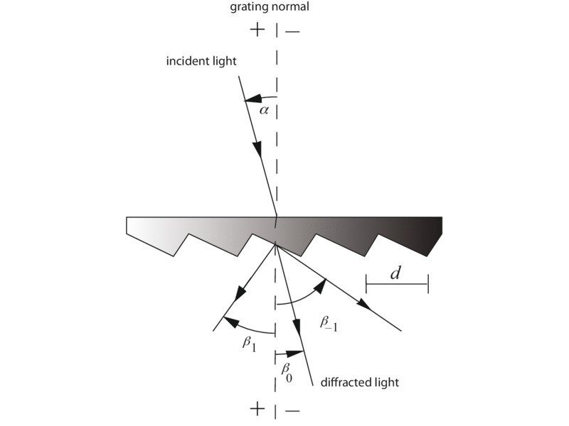
In certain types of instrumentation, transmission gratings (see Figure 1) are much more convenient to use than reflection gratings. The most common configuration involves converting cameras into simple spectrographs by inserting a grating in front of the lens. This configuration is often used for studying the composition of falling meteors or the re-entry of space vehicles, where the distant luminous streak becomes the entrance slit. Another application where high-speed lenses and transmission gratings can be combined advantageously is in the determination of spectral sensitivity of photographic emulsions.

Figure 1: Diffraction by a plane transmission grating. A beam of monochromatic light of wavelength λ is incident on a grating at angle α to the grating normal and diffracted along several discrete paths {βm}, for diffraction orders {m}. The incident and diffracted rays lie on opposite sides of the grating. The configuration shown, in which the transmission grating is illuminated from the back, is most common.

Transmission gratings can be made by stripping the aluminum film from the surface of a reflection grating. However, since the substrate is now part of the imaging optics, special substrates are used, made to tighter specifications for parallelism, and those used in the visible region are given a magnesium fluoride (MgF2) antireflection coating on the back to reduce light loss and internal reflections. The material used to form the substrate must also be chosen for its transmission properties and for the absence of bubbles, inclusions, striae and other imperfections, none of which is a concern for reflection gratings.

In most cases, relatively coarse groove frequencies are preferred for transmission gratings, although gratings up to 600 g/mm are furnished routinely. Experimentally, transmission gratings of 1200 g/mm have been used. Energy distribution on either side of the blaze peak is very similar to that of reflection gratings in the scalar domain. For wave-lengths between 220 and 300 nm, transmission gratings are made on fused silica substrates with a special resin capable of high transmission for these wavelengths.

Since transmission gratings do not have a delicate metal film they are much more readily cleaned. However, they are limited to spectral regions where substrates and resins transmit. Their main drawback is that they do not fold the optical path conveniently as a reflection grating does. Moreover, to avoid total internal reflection, their diffraction angles cannot be extreme. Even though the surface of the substrate is antireflection coated, internal reflections from the grating-air interface leads to some backward-propagating orders (that is, the transmission grating will also behave as a weak reflection grating); this limits the maximum efficiency to about 80%. The efficiency behavior of transmission gratings can be modeled adequately over a wide spectral range and for a wide range of groove spacing by using scalar efficiency theory.

For a reflection grating of a given groove angle θB with first-order blaze wavelength λB, the transmission grating with the same groove angle will be blazed between λB/4 and λB/3, depending on the index of refraction of the resin. This estimate is often very good, though it becomes less accurate for θB > 25°.

Although there are cases in which transmission gratings are applicable or even desirable, they are not often used: reflection gratings are much more prevalent in spectroscopic and laser systems, due primarily to the following advantages:

  • Reflection gratings may be used in spectral regions where glass substrates and resins absorb light (e.g., the ultraviolet).
  • Reflection gratings provide much higher resolving power than equivalent transmission gratings, since the path difference between neighboring beams (i.e., separated by a single groove) is higher in the case of the reflection grating – therefore transmission gratings much generally be wider (so that more grooves are illuminated) to obtain comparable resolving power.
  • Reflection grating systems are generally smaller than transmission grating systems since the reflection grating acts as a folding mirror.

Grating Prisms (GRISMS)

For certain applications, such as a direct vision spectroscope, it is useful to have a dispersing element that will provide in-line viewing for one wavelength. This can be done by replicating a transmission grating onto the hypotenuse face of a right-angle prism. The light diffracted by the grating is bent back in-line by the refracting effect of the prism. The device is known as a Carpenter prism, but is more commonly called a grism.

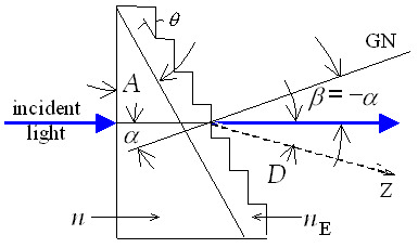
The derivation of the formula for computing the required prism angle follows (refer to Figure 12-2). On introducing Snell's law, the grating equation becomes

mλ= d (n sinα + n' sinβ)     (12-1)

where n and n' are the refractive indices of glass and air, respectively, and β < 0 since the diffracted ray lies on the opposite side of the normal from the incident rays (α > 0).

Taking n' = 1 for air, and setting α = –β = Φ, the prism angle, Eq. (12-1) becomes

mλ= d (n–1) sinΦ     (12-2)

In this derivation it is assumed that the refractive index n of the glass is the same (or very nearly the same) as the index nE of the resin at the straight-through wavelength . While this is not likely to be true, the resulting error is often quite small.

The dispersion of a grating prism cannot be linear, owing to the fact that the dispersive effects of the prism are superimposed on those of the grating. The following steps are useful in designing a grism:

  1. Select the prism material desired (e.g., BK-7 glass for visible light or fused silica for ultraviolet light).
  2. Obtain the index of refraction of the prism material for the straight-through wavelength.
  3. Select the grating constant d for the appropriate dispersion desired.
  4. Determine the prism angle Φ from Eq. (12-2).
  5. For maximum efficiency in the straight-through direction, select the grating from the Diffraction Grating Catalog with groove angle θ closest to Φ.
Grating prism (grism). The ray path for straight-through operation at one wavelength is shown. The refractive indices of the prism, resin and air are indicated as n, nE and n', respectively; also, Φ is the prism angle and θ is the groove angle. The incidence angle α and diffraction angle β are measured from GN, the grating normal.

Design equations for grism spectrometers may be found in Traub.

Grazing Incidence Systems

For work in the x-ray region (roughly the wavelength range 1 nm < λ < 25 nm), the need for high dispersion and the normally low reflectivity of materials both demand that concave gratings be used at grazing inci-dence (i.e., |α| > 80°, measured from the grating normal). Groove spacings of 600 to 1200 per millimeter are very effective, but exceptional groove smoothness is required on these gratings to achieve good results.

Echelles

A need has long existed for spectroscopic devices that give higher resolution and dispersion than ordinary gratings, but with a greater free spectral range than a Fabry-Perot etalon. This need is admirably filled by the echelle grating, first suggested by Harrison. Echelles have been used in a number of applications that require compact instruments with high angular dispersion and high throughput.

Echelles are a special class of gratings with coarse groove spacings, used in high angles in high diffraction orders (rarely below |m| = 5, and sometimes used in orders beyond m = 100). Because of spectral order overlap, some type of filtering is normally required with higher-order grating systems. This can take several forms, such as cut-off filters, detectors insensitive to longer wavelengths, or cross-dispersion in the form of prisms or low-dispersion gratings. The latter approach leads to a square display format suitable for corresponding types of array detectors; with such a system a large quantity of spectroscopic data may be recorded simultaneously. First-order design principles for echelle spectrometers using a cross-disperser have been developed by Dantzler.

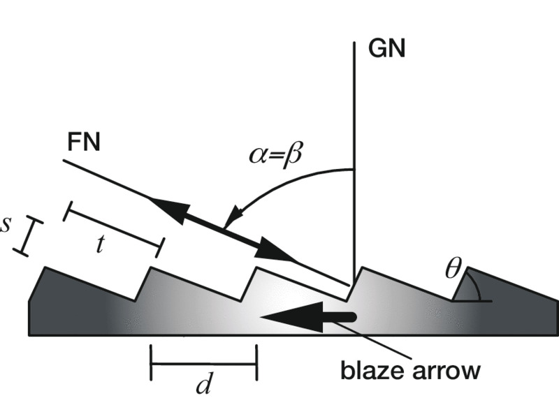
As seen in Figure 12-3, an echelle looks like a coarse grating used at such a high angle (typically 63° from the normal) that the steep side of the groove becomes the optically active facet. Typical echelle groove spacings are 31.6, 79 and 316 g/mm, all blazed at 63°26' (although 76° is available for greater dispersion). With these grating, resolving powers greater than 1,000,000 for near-UV wavelengths can be obtained, using an echelle 10 inches wide. Correspondingly high values can be obtained throughout the visible spectrum and to 20 μm in the infrared.

Echelle geometry for use in the Littrow blaze condition. The groove spacing d, step width t and step height s are shown. The double-headed arrow indicates that the grating is used in the Littrow configuration (α = β ), and β was chosen to equal the groove angle θ to satisfy the blaze condition. GN is the grating normal and FN is the facet normal. The blaze arrow (shown) points from GN toward FN.

Since echelles generally operate close to the Littrow mode at the blaze condition, the incidence, diffraction and groove angles are equal (that is, α = β = θ) and the grating equation becomes

= 2d sinβ = 2d sinθ = 2t     (12-3)

where t = d sinθ is the width of one echelle step (see Figure 12-3).

The free spectral range is

Fλ = λ/m    (2-29)

which can be very narrow for high diffraction orders. From Equation (12- 3), m = 2t/λ , so

Fλ = λ2/2t     (12-4)

for an echelle used in Littrow. In terms of wavenumbers*, the free spectral range is

Fσ = Δλ/λ2 = 1/2t     (12-5)

The linear dispersion of the spectrum is, from Eq. (2-16),

r' ∂β/λ =  mr'/d cosβ = mr'/s =  r'/s(2t/λ)  (12-6)

where s = d cosβ = d cosθ is the step height of the echelle groove (see Figure 12-3). The dispersion of an echelle used in high orders can be as high as that of fine-pitch gratings used in the first order.

The useful length l of spectrum between two consecutive diffraction orders is equal to the product of the linear dispersion and the free spectral range:

l = r'λ/s     (12-7)

For example, consider a 300 g/mm echelle with a step height s = 6.5 μm, combined with an r' = 1.0 meter focal length mirror, working at a wavelength of λ = 500 nm. The useful length of one free spectral range of the spectrum is l = 77 mm.

Typically, the spectral efficiency reaches a peak in the center of each free spectral range and drops to about half of this value at the ends of the range. Because the ratio λ/d is generally very small (<< 1) for an echelle used in high orders (m >> 1), polarization effects are not usually pronounced, and scalar methods may be employed in many cases to compute echelle efficiency.

The steep angles and the correspondingly high orders at which echelles are used make their ruling much more difficult than ordinary gratings. Periodic errors of ruling must especially be limited to a few nanometers or even less, which is attainable only by using interferometric control of the ruling engine. The task is made even more difficult by the fact that the coarse, deep grooves require heavy loads on the diamond tool. Only ruling engines of exceptional rigidity can hope to rule echelles. This also explains why the problems escalate as the groove spacing increases.

An echelle is often referred to by its "R number", which is the tangent of the blaze angle θ:

R number = tanθ = t/s     (12-8)

The lengths s and t are shown in Figure 12-2. An R2 echelle, for example, has a blaze angle of tan–1(2) = 63.4°; an R5 echelle has a blaze angle of tan–1(5) = 78.7°.

 R number Groove angle 
 R1  45.0°
 R2  63.4°
 R3  71.6°
 R3.5  74.1°
 R4  76.0°
 R5  78.7°
R6 80.5◦

Instruments using echelles can be reduced in size if the echelles are “immersed” in a liquid of high refractive index n (see Figure 12-4). This has the effect of reducing the effective wavelength by n, which is equivalent to increasing the diffraction order, resolving power and dispersion of the echelle (compared with the same echelle that is not immersed). A prism is usually employed to couple the light to the grating surface, since at high angles most of the light incident from air to the high-index liquid would be reflected. Often an antireflection (AR) coating is applied to the normal face of the prism to minimize the amount of energy reflected from the prism.

Immersed Gratings

Unlike a grism, an immersed grating couples a prism to a reflection grating rather than a transmission grating. Instruments using gratings can be reduced in size if the gratings are “immersed” in a material of high refractive index n, usually an optically transmissive liquid or gel (see Figure 12-4). This has the effect of reducing the effective wavelength by n, which is equivalent to increasing the diffraction order, resolving power and dispersion of the grating (compared with the same grating that is not immersed). A prism is usually employed to couple the light to the grating surface, since at high angles most of the light incident from air to the high-index liquid would be reflected. Often an antireflection (AR) coating is applied to the normal face of the prism to minimize the amount of energy reflected from the prism.