Technical Note:
Phase and Amplitude Modulator Definitions of Characteristics
Aperture
The diameter of the mechanical aperture at the input and output of the modulator. The aperture aids optical alignment and ensures that the beam passes through the center of the crystal.
Connector
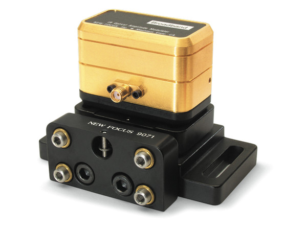
All modulators have female SMA input connectors. To convert to a BNC connector, use the Model 1225 adapter.
Impedance
The input impedance seen by your electronic driver. The broadband devices are a capacitive load, and the resonant modulators are matched to 50 Ω.
Material
In our phase modulators we use MgO-doped LiNbO3 or KTP crystals. In our amplitude modulators we use both LiNbO3, and MgO-doped LiNbO3.
Maximum Optical Intensity
The maximum optical intensity of a 1-mm-diameter beam that can be passed through the crystal without causing photorefractive damage. Note that this optical damage threshold is strongly wavelength dependent.
Maximum RF Power
The maximum recommended RF drive power. Above this power, the electronic components will saturate or thermal effects in the crystal (such as thermal lensing) will become a problem.
Maximum VΠ
The voltage required to achieve a Π phase shift at 1.06 µm. It is proportionately smaller at shorter wavelengths. The VΠ is much smaller for resonant devices because the resonant circuit provides significant voltage enhancement.
Metric Versions
Modulators are equipped with a plastic base that can have either English (1/4-20) or metric (M6) threaded holes for mounting. To specify a metric version when ordering, add an “M” after the model number.
Modulation Depth (Phase Modulators Only)
The resulting phase change when 1 V is applied to the modulator. The modulation depth is specified at 1.06 µm. Since it is proportionately larger at shorter wavelengths, the modulation depth at 532 nm is twice that at 1.06 µm. The modulation depth is much larger for resonant phase modulators because the resonant circuit provides voltage enhancement when operating on resonance.
Operating Frequency
The range of electrical frequencies over which a modulator can operate. For resonant modulators, the specific resonant frequency can be chosen anywhere within this range when ordering the modulator.
RF Bandwidth
The operating range of a particular device, otherwise known as the 3-dB frequency. It is the frequency range over which at least one-half of the electrical drive power will be transferred to the modulator. This is equivalent to the point at which the modulation depth has decreased by a factor of 2, since modulation is proportional to electrical field strength and not electromagnetic power.
Type
Broadband modulators can operate from DC–100 kHz to 100–250 MHz. Resonant modulators operate at a single frequency and have much lower VΠ.
VSWR
The voltage standing-wave ratio (VSWR) is defined as the ratio between the maximum and minimum voltages along a standing wave that results from electrical reflections due to an impedance mismatch. A VSWR value of 1 indicates a perfectly matched system. Since the VSWR is related to the reflection coefficient R by it tells you how much electrical power will be reflected back to
your driver. Excessive reflected RF power can damage your source. A VSWR of 1.5 corresponds to 4% of the incident RF power reflected back to the driver.
Wavelength
The wavelength range of the crystal’s AR coating. For our phase modulators, we offer two broadband AR coatings, 0.5–0.9 µm and 1.0–1.6 µm. For our amplitude modulators, we offer only a near-IR version. (Our amplitude modulators use LiNbO3 crystals, which are susceptible to photorefractive damage at shorter wavelengths.)
AR coatings result in 1% maximum reflectivity per surface. Combined with a typical absorption loss of 0.3%/cm , the typical insertion loss is 3.2% for the phase modulators, which use one 4-cm crystal, and 5.2% for the amplitude modulators, which use two 2-cm crystals.