Linear Translation Stage Technology Guide
The function of a linear translation stage is to constrain motion along an ideal straight line. Any undesired motion in constrained directions will contribute to deviation from the ideal trajectory and/or final position. Contributors to deviations include load forces and issues in designing and constructing a perfect linear translation stage in a world where perfect machining and ideal materials do not currently exist. For detailed information on precision positioning please see Manual Positioning Basics, or see Motion Basics and Standards if you are interested in automated motion control.
Linear Translation Stage Design Considerations
Construction Materials
Each material used in the design of a linear translation stage has its own unique set of advantages and disadvantages. The following is a summary of the properties for the most common materials used in motion mechanics.
| Parameter | Steel | Aluminum | Brass | Granite |
|---|---|---|---|---|
| Young's modulus (stiffness), E (Mpsi) | 28 | 10.5 | 14 | 7 |
| Density, ρ(lb/in3) | 0.277 | 0.097 | 0.307 | 0.1 |
| Specific Stiffness, E/ρ | 101 | 108 | 45.6 | 70 |
| Thermal Expansion, α(µin/in/°F) | 5.6 | 12.4 | 11.4 | 4 |
| Thermal Conduction, c (BTU/hr-ft-°F) | 15.6 | 104 | 67 | 2 |
| Relative Thermal Distortion, α/c | 0.36 | 0.12 | 0.17 | 2 |
Aluminum
Features: Aluminum is a lightweight material, resistant to cold flow or creep, with good stiffness-to-weight ratio. It has a relatively high coefficient of thermal expansion, but it also has a high thermal conductivity, making it a good choice in applications where there will be thermal gradients or where rapid adjustment to temperature changes is required. Aluminum is fast-machining, cost-effective, and widely used in stage structures. Aluminum does not rust, and corrosion is generally not a problem in a typical user's environment, even when the surface is unprotected. It has an excellent finish when anodized.
Limitations: Anodized surfaces are highly porous, making them unsuitable for use in high vacuum.
Coatings: Anodized aluminum provides excellent corrosion resistance and a good finish. Black is the color most often used. Anodizing hardens the surface, improving scratch and wear resistance. Aluminum may also be painted, with excellent results.
Steel
Features: Steel has a high modulus of elasticity, giving it very good stiffness (nearly three times that of aluminum) and good material stability. It also has about half the thermal expansion of aluminum, making it an excellent choice for stability in typical user environments where there are uniform changes in temperature. Stainless Steel is well suited to high vacuum applications.
Limitations: Machining of steel is much slower than aluminum, making steel components considerably more expensive. Corrosion of steel is a serious problem, but stainless steel alloys minimize the corrosion problems of other steels.
Coatings: Steel parts are generally plated or painted. Platings are often chrome, nickel, rhodium, or cadmium. A black oxide finish is often used on screws and mounting hardware to prevent rust. Stainless steel alloys avoid the rust problems of other steels. They are very clean materials that do not require special surface protection. A glass-bead blasted surface will have a dull finish so that it does not specularly reflect.
Brass
Features: Brass is a heavy material, denser than steel, and fast machining. The main use of brass is for wear reduction; it is often used as a dissimilar metal to avoid self-welding effects with steel or stainless steel lead-screws or shafts. Brass is used in some high precision applications requiring high resistance to creep and can be diamond turned for extremely smooth surfaces.
Limitations: Compared to aluminum and steel, brass has a less desirable stiffness-to-weight ratio. Moreover, although the thermal expansion of brass is similar to that of aluminum, its thermal conductivity is nearly a factor of two worse.
Coatings: For optical use, brass is usually dyed black. In other cases, it may be plated with chrome or nickel for surface durability.
Stiffness
Stiffness is a measure of the amount of force required to cause a given amount of deflection. Force and deflection are proportional and related by the equation:
Δx = (1/E) * xF/A
where F and Δx are force and deflection, respectively, x is the nominal length, and A is the surface area perpendicular to the force. E is a material-dependent constant called the modulus of elasticity, Young's modulus, or simply the stiffness of a material. Larger values of E mean greater material stiffness.
Thermal Expansion
Thermal expansion is the change in size or shape of an object, such as a stage, due to a change (increase or decrease) in temperature. The amount of change is dependent on the size of the component, the degree of temperature change, and the material used. The equation relating dimensional change to temperature change is:
ΔL = αLΔT
where α is the material-dependent coefficient of thermal expansion.
Thermal Conductivity
Some materials, such as aluminum, are good choices when temperature change across the component is non-uniform. This occurs when mounting a heat source, such as a laser diode. Because the diode is hotter than the surrounding environment, it dissipates heat through the mount, setting up a temperature gradient along the stage. If the material does not readily dissipate the heat, then distortions caused by thermal gradients can become significant.
The distortion caused by non-uniform temperature changes is proportional to the coefficient of thermal expansion, α, divided by the coefficient of thermal conductivity, c. Relative thermal distortion = α/c.
If the ambient operating temperature of the component is much different from the room temperature, then close attention should be paid to components made with more than one material. In a linear stage, for example, if the stage is aluminum while the bearings are stainless steel, the aluminum and steel will expand at different rates if the temperature changes, and the stage's bearings may lose preload or the stage may warp due to stresses built up at the aluminum–steel interface.
Material Instability
Material Instability is the change of physical dimension with time (also called cold flow or creep). For aluminum, brass and stainless steel, the period of time required to see this creep may be on the order of months or years.
Bearing and Flexure Mechanisms
The load and trajectory performance of a translation or rotation stage is primarily determined by the type of bearing or flexure used. Bearings permit smooth low-friction rotary or linear movement between two surfaces. Bearings employ either a sliding (dovetail) or rolling action (ball or crossed-roller). In both cases, the bearing surfaces must be separated by a film of oil or other lubricant for proper performance. Flexures, however, provide a means of translation that requires no lubrication and is virtually free of the stiction normally associated with bearings. This type of mechanism, when used in a translation stage, limits linear travel range to just a few millimeters.
Dovetail Slides
Dovetail Slides are the simplest types of linear stages and are primarily used for manual positioning. They consist of two flat surfaces sliding against each other with the geometry shown below. Dovetail slides can provide long travel, and have relatively high stiffness and load capacity. They are more resistant to shock than other types of bearings and are fairly immune to contamination. However, they do have relatively high stiction, and their friction varies with translation speed, which makes precise control difficult and limits sensitivity.
Ball Bearings
Ball Bearing and Double Row Ball Bearing slides reduce friction by replacing sliding motion with rolling motion. Balls are captured in guideways by means of vee-ways or hardened steel rods. The guide ways are externally loaded against the balls to eliminate unwanted runout in the bearings. Even with this preload, the friction is very low resulting in extremely smooth travel. Ball bearing slides are relatively insensitive to contamination because each ball contacts the guideways at only a single point, allowing debris to be pushed out of the way.
With a vee-groove bearing way, ball bearings have a lower load capacity than crossed-roller bearings, since the contact area available to transmit loads is smaller - so in order to carry the same size load, the balls would need to have a larger diameter or be greater in quantity.
If the mating bearing ways are ground with either a Gothic Arch or circular groove, the closer conformity to the balls' radii allows the use of smaller balls than with flat ways. The arch approximates a vee-shaped way with the load effectively split at angles of about 45 degrees with the vertical into two loads on the way.
A circular shaped way has a higher load capacity, but the balls bear the load on the bottom of the groove, which can result in side play for loads that are perpendicular to the direction of motion.
Crossed-Roller Bearings
Crossed Roller Bearings offer all of the advantages of ball bearings with higher load capacity and higher stiffness. This is a consequence of replacing the point contact of a ball with the line contact of a roller. Due to the averaging characteristics of line contacts, angular and linear deviations are generally below those found in ball bearings. However, crossed-roller bearings require more care during manufacture and assembly, resulting in higher costs. Crossed-roller bearings are also more sensitive to contamination because they are less effective at pushing foreign particles away from contact with the guideways.
Flexure Mechanisms
A flexure is stictionless positioning mechanism which uses the elastic deformation of a material to provide translation. A flexure may be made from various materials but generally is made from high-yield-strength spring steel. A flexure must be designed such that the maximum stress experienced by the material does not exceed its yield strength. If this is not done, the flexure will have permanent deformation and will no longer function normally. Flexures can be used in either single or multi-axis translation stages and, due to their size, can provide several axes of motion in a very compact package. In use, flexure-enabled translation normally approximates a straight-line with a slight circular path, so there is a second-order cross coupling between axes. The stage platform moves vertically as it is displaced longitudinally. This is called arcuate motion and is largest at the limits of the stage's travel range
Drive Options
Manual Actuators
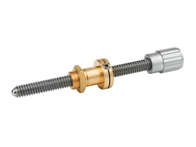
Manual actuators are the simplest and lowest cost options for positioning. A manual actuator can be described as a high sensitivity lead screw with a knurled knob. On many manual linear translation stages, like our 460A-X or 423, the nut of the screw is fixed to the stage body, and the screw itself moves back and forth (in contrast to lead screw driven systems, where the nut moves back and forth). Springs press the carriage against the screw tip to make good contact and to preload the screw to eliminate backlash.
Fine Adjustment Screws
High resolution, ultra-fine Adjustment Screws and Nudgers, like those found in Newport's AJS Series, use rolled threads for smooth actuation and have a ball tip to reduce wear and minimize undesirable lateral motion. Featuring a pitch between 80 and 127 threads per inch (TPI), these screws permit sub-micron adjustments. When no position readout is required, fine adjustment screws are not only a lower cost option, but they also offer superior sensitivity compared to metric micrometer screws, which have 50 threads per 25 mm. Examples where position readout is unnecessary can be found when position may be monitored from the orientation or position of a laser beam or from the amount of optical power coupled through a system.
Micrometer Heads
Micrometer heads are the adjustment mechanism of choice if accurate position read-out, like repeatable positioning, is needed. Standard metric Micrometer Heads feature 50 threads per 25 mm and have a scale in units of 10 µm. An additional vernier - available on some versions - allows position readings with a resolution of 1 µm.
Differential Micrometer Screws
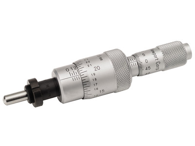
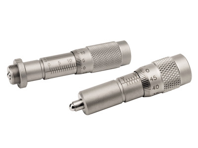
When resolution of much less than one micron is needed, a differential screw is recommended. These devices use the difference between two screws of nearly the same pitch to produce very fine motion. The motion achieved equals the difference between the two screw pitches. This is illustrated below. The effective pitch is given by:
1/Peff = 1/P1 – 1/P2
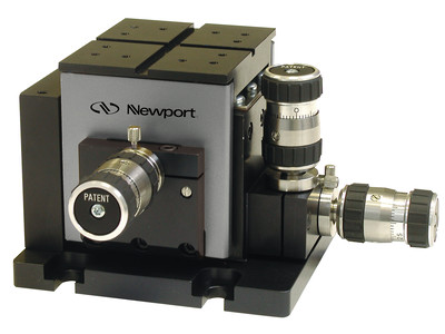
For example, in the patented DM-13 differential micrometer screw offered by Newport, the two screw pitches used have 20 threads per cm for the standard coarse adjustment micrometer barrel and 21.05 threads per cm (200 threads per 9.5 cm) for the differential barrel. The resultant effective pitch is equivalent to 400 threads per cm. This micrometer has a sensitivity of 0.07 µm.
Motorized Actuators
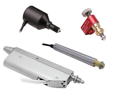
Motorized Linear Actuators provide customers the ability to upgrade and motorize manual linear translation stages for remote and/or computer control. When selecting a motorized linear actuator for use with one of our linear translation stages please refer to our Stage to Actuator Selection Guide for information on compatibility.
Vacuum Compatibility
Many products within this catalog can be vacuum prepared. Please look for the Vacuum Compatible statement on the specific product page. Vacuum Compatible products are prepared for 10-6 Torr. If you require products specially prepared for 10-3 Torr, or greater than 10-6 Torr environments, please contact our technical staff for a quotation. For those products not designated as vacuum compatible, we may still be able to prepare for vacuum environments. However, these would require special quoting. Please contact our technical staff to discuss your needs.
Vacuum Preparation
Preparation for vacuum environments depends on the vacuum you wish to maintain. The word “vacuum” does not adequately specify the conditions for a specific application. Acceptable levels of outgassing, mass loss and volatile condensable materials can vary with the application, pumping capacity, temperature, etc. It is, therefore, essential that the specific requirements be reviewed and understood prior to placing any component in a vacuum environment.
10-3 Torr environments: In general terms, a vacuum of 10-3 Torr requires minimal change to many of our products with the possible exception of lubricants. In this environment, it is not uncommon to use anodized parts and limited use of plastics should not pose any problems.
10-6 Torr environments: Components used in a vacuum of 10-6 Torr are specially prepared for this environment. Many of the materials used in standard components will outgas in a high vacuum, resulting in a “virtual” leak, which limits the ability to maintain a high vacuum. Highly porous anodized aluminum surfaces can trap large amounts of air molecules, resulting in significant outgassing. For those components, within this catalog, specified as Vacuum Compatible we perform the following in preparation:
- Products with anodized aluminum are created without anodize. As such, we only use unanodized aluminum, stainless steel or equivalent materials.
- Plastic knobs and handles are either removed or replaced (at additional cost) with high vacuum materials such as steel or Delrin. In some cases, you may choose to maintain the plastic knob due to incremental costs associated with producing an alternative design. In spite of plastics permeability it is common to use plastics in vacuum systems because of their insulating properties and price.
- Holes not tapped through are vented; or special vented hardware is used.
- Hardware and lubricants are changed to special vacuum compatible materials.
- Finished units are completely cleaned and sealed in appropriate packaging material.
Additional vacuum preparation steps, or preparation for vacuums of greater than 10-6, require special handling, including baking the product in a vacuum. If you have requirements at this level, please contact our technical staff to discuss the options available.