Improving Detector Performance
The constantly improving technology of detectors and wide selection of materials and detection methods allows most light detection needs to be satisfied by fairly simple systems. At the same time, with so many choices, selecting the best system can be confusing.
Look Only For What You Want to See
This is the main theme of this section. We talk about minimizing the influence of noise understood in the broadest sense of the word, i.e. any contribution which lessens our ability to get a meaningful measurement.
The suggestions below may sound trivial, but we offer them anyway, since we continue to amaze ourselves with how often we forget to go through this simple analysis when setting up a new experiment.
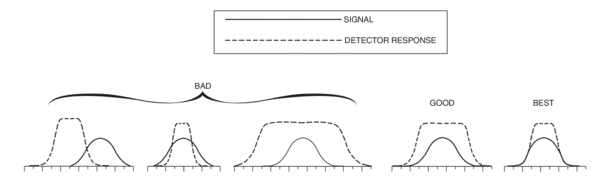
Figure 1 graphically depicts what we'll be talking about - the four criteria for choosing the best match of detector response to signal characteristics. These sketches will look the same if the abscissas are labeled:
- Wavelength
- Bandwidth
- Time
- Field of View
This figure shows a variety of poor matches, a good match and the “best” match.
Wavelength
The detector sensitivity must cover the wavelength range of your signal. If the detector’s sensitivity wavelength range exceeds that of the signal, any radiation outside of the signal range will contribute to noise. Use a bandpass filter to narrow the range of wavelengths seen by the detector. If the detector and signal ranges miss each other partially, then some of the signal information is lost. The “Good” and “Best” cases in Figure 1 demonstrate full capture of signal information with wavelength mismatch contributing little or nothing to system noise.
Bandwidth
Frequency bandwidth is the most often adjusted factor in trying to reduce noise contribution. This is because it very explicitly enters the noise equations in the form of
(BANDWIDTH)1/2
and we are reminded of it with the frequent appearance of the Hz-1/2 expression in the units field of white, frequency independent, noise contributions. This applies to Johnson and shot noises. Moving up in frequency to minimize the 1/f noise is another form of bandwidth control. AC detection methods, to be discussed in more detail on the next page, take advantage of various forms of electronic and digital filters to match the detection bandwidth to the frequency spectrum representing the rate of change of the useful signal. AC methods are particularly beneficial in the infrared part of the spectrum due to the large amount of background radiation.
Time
Particular events may occur at specific time intervals and for specific lengths of time. There are a number of techniques to first create this periodic behavior, if it is not naturally occurring, and then using it to improve the signal to noise ratio. It is important that the characteristic signal frequency be as different as possible from the natural modulation frequencies of the noise sources (60 or 50 Hz line frequencies and their harmonics are notorious). Oriel Optical Choppers, and electronically modulated sources, are frequently used. Some “good” modulation frequencies include 30 Hz (25 Hz), 90 Hz (75 Hz), etc. Higher modulation frequencies are required for measuring fast changing signals. Narrow bandwidth AC detection methods, of which the lock-in technique is the most widely used, are used to take advantage of the signal modulation. Gated averagers or integrators are used to improve the signal to noise ratio in the measurement of pulsed sources.
Field of View
This is a very important criterion for infrared detectors. Because room temperature objects emit infrared photons, particularly in the vicinity of 10 µm, you need to narrow the field of view to receive radiation mostly from the source of interest. Imaging and aperturing should be put to use as this effort will pay big dividends in providing you with meaningful and reproducible results.
General Noise Reduction Techniques
Temperature Control
All detectors and signal conditioning electronics have some temperature dependence in their noise and responsivity characteristics. You will obtain more reproducible results if you stabilize the thermal environment of your experiment. You will typically improve your detectivity limits by cooling your detector to operate below room temperature. The degree of gain in performance depends on detector type and post detection electronics. However, you will do significantly better with cooled photon detectors which respond to the infrared part of the spectrum. Dark currents diminish a factor of 2 every 5 to 20 °C, depending on the system’s characteristic energy, e.g. band gap or work function.
Ratios
No source is perfectly stable. Whenever possible, ratio your response signal to that of the source to obtain the most accurate results.
AC Techniques
It may sound funny to use AC techniques to measure DC signals but it actually is the best way in practice. You can encode your signal with a known modulation and then use this characteristic modulation to discriminate against noise contribution which will have its power spread over a different and wider band of frequencies.
An AC coupled amplifier with a narrow band filter centered on the modulation frequency will help you significantly increase your signal to noise ratio. You can narrow the filter frequency pass band only to the limit of your modulator stability. If the noise contribution is still too much you will have to revert to lock-in techniques. These depend on the amplifier actively tracking the modulator frequency and thus allowing much narrower band filtering to be used. We do a lot of this filtering in the digital part of our Merlin™ Radiometer System, eliminating phase and amplitude drifts associated with the older analog lock-ins.
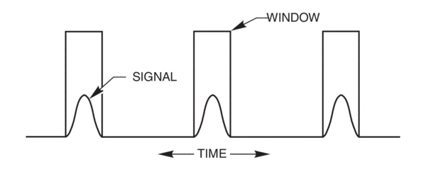
Gated Integration/Boxcar Averaging
These techniques take their name from the appearance of the pictorial representation of the process, Figure 2. Gates, boxes, or “windows” are used to define the times during which the electronics acquire signal. During those gated times, the signal to noise ratio is already improved, since noise contributions which would be accumulated during the off times are absent. The process, when repeated for N pulses, will lead to signal to noise ratio improvement of N1/2 if the noise is of the white variety, Johnson or shot. This is because the integrated signal contribution increases as N, while noise contribution increases only as N1/2.
Beware
AC coupled detectors may be subject to DC saturation (from background) and thus loss of linearity. You must understand your detector’s DC response limits when using it in an AC coupled mode of operation.
Watch out for frequency roll-offs. The post detection electronics frequently limits the response of your detector. There may be multiple bandwidths associated with a particular piece of equipment, which depend on the selected gains.
Rules of Thumb
You cannot beat Johnson noise, but you can minimize its contribution to the S/N ratio.
You should try to make the bias current shot noise, the dominant AC noise contributor in a PMT based detection system. Make this noise three or more times bigger than Johnson noise and you have effectively negated the influence of Johnson noise on the system's S/N behavior. In low light situations, start by choosing your transimpedance gain to be the maximum allowed by bandwidth requirements. Note the AC noise at the PMT output with zero volts of bias (Johnson Noise). Now, raise your bias voltage, within the safe range of the tube, until the dark current AC shot noise is about three times greater than Johnson noise, i.e. you want to see variance about four times the level of zero bias case. You are now ready to measure your signals with a high degree of linearity, since the shot noise and photon signal and noise are amplified the same amount in the electron multiplier chain. If you only intend to measure very low signals then you should consider photon counting.