Fiber Optic Physics
Optical fiber and fiber optic cables are used as a means to transport optical energy and information over short or long distances. In combination with semiconductor laser diodes and photoreceivers, optical fibers have enabled the rapid development and proliferation of fiber optic telecommunication systems over the past thirty years. Optical fibers are circular cross section dielectric waveguides consisting of a central core surrounded by a concentric cladding with a slightly lower (by ≈ 1%) refractive index. They are typically made of silica with index-modifying dopants such as GeO2. A fiber optical cable is an optical fiber enclosed in a protective coating. This allows for ease of handling, reduces cross talk between adjacent fibers, and suppresses loss that occurs when fibers are pressed against rough surfaces. In addition to the benefits of light transmission, the confinement of light to a small area within the core of an optical fiber has enabled the development of fiber lasers (see Types of Lasers) and photonic crystal fibers. This section discusses the fundamental physics of optical fibers, their practical implementation, and the various types of optical fibers.
Basics of Optical Fibers
Figure 1 illustrates the directions of incident rays of light when they encounter an interface with a rarer medium, i.e., n2 < n1 as when light goes from glass to air. Rays 1 and 2 refract according to Snell's law. At a specific incident angle known as the critical angle θc, the angle of refraction is 90° (Ray 3), causing the light to travel along the interface between the two media. For any angle greater than θc, there is no refracted ray and the light experiences total internal reflection (TIR), causing it to simply obey the laws of reflection (as exemplified by Ray 4). When light is incident from a medium of higher index, determination of θc is accomplished by using Snell's law: θC = arcsin(n2/n1). As shown below, it is the phenomenon of TIR that enables propagation of light in optical fibers.
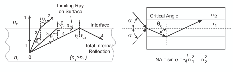
An optical fiber is a circular dielectric waveguide whose core has a higher index of refraction than the cladding. As shown in Figure 1, light will be confined to the core if the angular condition for TIR is met. The NA of a fiber is defined as the sine of the largest angle (α) an incident ray can have for TIR in the core. Qualitatively, NA is a measure of the light gathering ability of a fiber. It also indicates how easy it is to couple light into a fiber. The fiber geometry and composition determine the discrete set of electromagnetic fields, or fiber modes, which can propagate in the fiber. There are two broad classifications of modes: radiation modes and guided modes. Rays launched outside the angle specified by a fiber's NA will excite radiation modes. These modes carry energy out of the core where it is quickly dissipated. Rays launched within a fiber's NA typically give rise to guided modes which are confined to the core. These modes propagate energy along the fiber, transporting information and power. If the fiber core is large enough, it can support many simultaneously guided modes, i.e., multimode propagation. When light is launched into a fiber, the modes are excited to varying degrees depending on the conditions of the launch, e.g., input cone angle, spot size, axial centration, and can take on a variety of spatial distributions. Much like for the transverse modes of a laser (see Laser Light Characteristics), the lowest-order mode of an optical fiber has a near-Gaussian spatial distribution and therefore possesses many of the same benefits. This is why single single-mode operation is often desired in a fiber. The normalized frequency parameter of a fiber, also called the V number, is a useful specification in this regard. It describes the number of modes at a given wavelength based on the fiber's NA and its core radius.
Light power propagating in a fiber decays exponentially with length due to absorption and scattering losses (see Figure 2). Attenuation is the single most important factor in fiber optic telecommunication systems, as it directly impacts acceptable signal levels. In the NIR and VIS regions, the small absorption losses of pure silica are due to tails of absorption bands in the FIR and UV. Impurities, notably water in the form of hydroxyl ions, are much more dominant causes of absorption in commercial fibers. Recent improvements in fiber purity have reduced attenuation losses to the order of 0.1 dB/km. Scattering losses also contribute to attenuation in the form of small-scale index fluctuations in the fiber when it solidifies and irregularities in the core diameter and geometry.
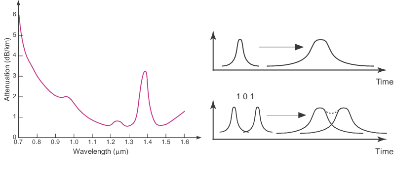
The bandwidth of an optical fiber determines its data rate. The mechanism that limits a fiber's bandwidth is known as dispersion. Dispersion is the spreading of the optical pulses as they travel down the fiber. The result is that pulses begin to spread into one another and the symbols become indistinguishable (see Figure 2). Dispersion limits both the bandwidth and the distance that information can be transported. There are two main categories of dispersion: intramodal and intermodal. There are two distinct types of intramodal dispersion: chromatic dispersion and polarization-mode dispersion. Chromatic dispersion is simply the result of the variation in the material's refractive index with wavelength. Polarization mode dispersion is due to orthogonal polarization modes in a fiber traveling at different speeds due to birefringence. Intermodal dispersion occurs because different propagating modes travel with different velocities. Therefore, this category of dispersion only applies to multimode fibers.
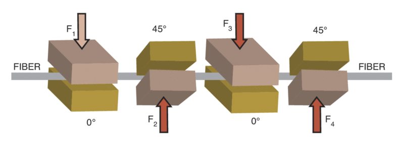
A single-mode fiber supports a mode which consists of two orthogonal polarization modes. This is the result of the asymmetry in the fiber core cross-section. Normally, external stresses are randomized and the resulting induced birefringence helps to scramble or randomize the polarization. A specialty fiber known as a polarization-maintaining fiber intentionally creates a consistent birefringence pattern along its length. This is accomplished by modifying the geometry of the fiber and the materials used to create a large amount of stress in one direction. This large induced birefringence dominates the random birefringence, allowing polarization to be maintained during propagation within the fiber. Controlling the polarization state in an optical fiber is similar to the free space control using waveplates via phase changes in the two orthogonal states of polarization (see Polarization Optics). This is accomplished by applying stress-induced birefringence to a fiber. This induces a retardation enabling the creation of a waveguide-based waveplate. Figure 3 shows one such polarization device which consists of a fiber squeezer that rotates around the optical fiber. Applying a pressure to the fiber produces a linear birefringence, effectively creating a fiber wave plate whose retardation varies with the pressure.
Fiber Coupling
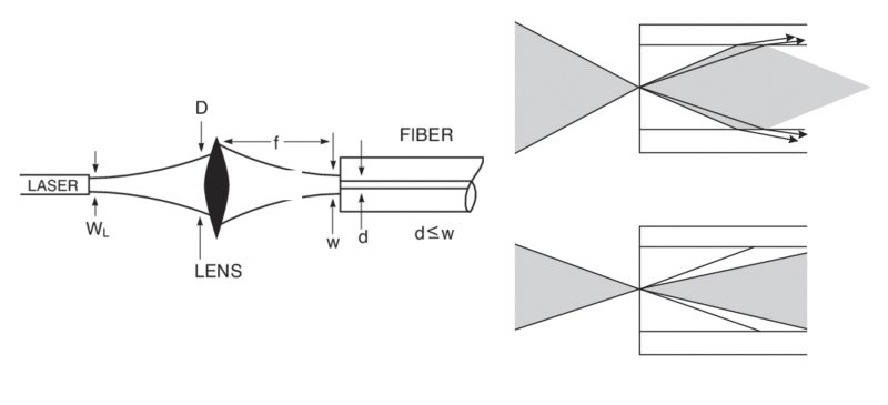
The characteristics of the focused beam (typically a laser beam) must match the fiber parameters for good coupling efficiency. The general guidelines are:
- The focused spot should be comparable to the core size.
- The focused beam should be centered on the fiber core.
- The incident cone angle should not exceed the NA of the fiber.
Conditions (1) and (2) are illustrated on the left side of Figure 4 and condition (3) is illustrated on the right side of the figure. The first two conditions are easy to accommodate for multimode fibers owing to their large core diameters. Consequently, good coupling efficiency is achieved in a multimode fiber by matching the coupling lens to the fiber NA. Coupling into single-mode fibers is a fundamentally more difficult problem. Single-mode fibers have small core diameters requiring more opto-mechanical components that enable coupling of the focused beam with sub-micron positioning resolution. Furthermore, the mode of the incident laser light must match the mode of the fiber. In other words, the coupling efficiency depends upon the overlap integral of the Gaussian mode of the input laser beam and the nearly Gaussian fundamental mode of the fiber.
Fiber Types
There are a large variety of optical fibers available that can exhibit very different geometries as shown in Figure 5. Standard single-mode fibers for telecommunications applications have small core diameters (< 10 µm) whereas multimode fibers have core diameters between sixty and several hundred microns. The latter can also have index profiles that are either graded or stepped. Specialty fibers are also common, including polarization maintaining fiber, high power delivery fiber optic cables, bend-insensitive optical fiber, and fibers for extreme temperature conditions. Due to their ubiquity and utility, two specific types of specialty fibers are described in more detail below: rare earth doped fibers and photonic crystal fibers (PCFs).
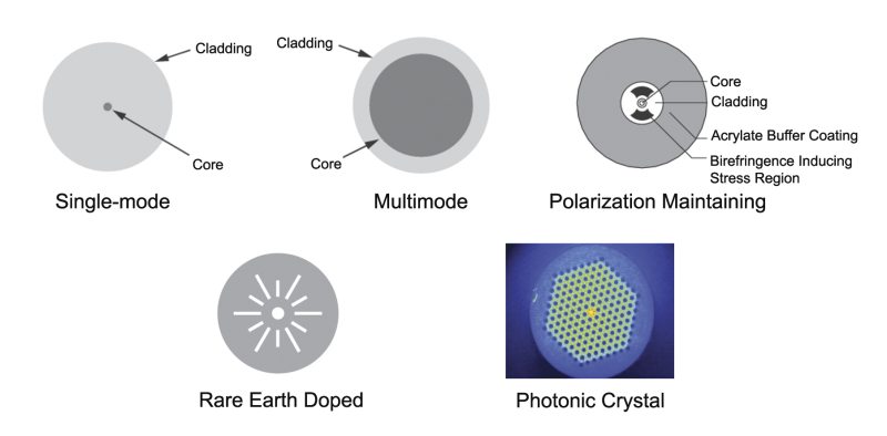
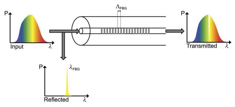
Rare earth doped fibers are particularly important for fiber lasers since these dopants, e.g. Nd, Yb, and Er-Yb co-doped, can act as laser gain media (see Types of Lasers). The use of double-clad rare earth doped fibers can allow for efficient matching of the pump beam, whether it is delivered by free-space focusing or via another optical fiber. These doped fibers can also be used as photosensitive fibers for fabricating FBGs. A Bragg grating is a periodic modulation in a material's index of refraction that enables reflection of light with a wavelength of twice the grating period. High quality FBGs can be constructed by exposing photosensitive optical fibers to periodic patterns of UV light (rare earth dopants absorb strongly in the UV). The grating forms when the fiber is exposed to a periodic pattern of UV light, typically generated with a phase mask. Such fabrication methods are clearly attractive from a production point of view since they allow for rapid and reliable manufacturing. FBGs enable high reflectivity (up to 99%) over a narrow wavelength band (see Figure 6), which is useful for producing a cavity mirror in a fiber laser or as spectral filters in fiber optic telecommunications systems.
A photonic crystal is a microstructured material in which there is a periodic variation in the index of refraction as a function of position. In PCFs, this periodic variation is achieved through a regular pattern of voids, or air holes that run parallel to its axis (see Figure 5). Unlike traditional fibers, both the core and cladding are made from the same material. All the waveguiding properties in a PCF thus derive from the presence of the voids. PCFs are generally divided into two main categories: index guiding fibers that have a solid core, and photonic bandgap fibers that have periodic microstructured elements and a core of low index material, e.g. hollow core. PCFs provide characteristics that ordinary optical fibers cannot, such as single-mode operation from the UV to IR with large mode-field diameters, exceptionally high nonlinearity, NA values ranging from very low to about 0.9, and optimized dispersion properties. Applications of PCFs are found in a wide range of research fields like spectroscopy, metrology, biomedicine, imaging, telecommunication, industrial machining, and defense & homeland security.

For additional insights into photonics topics like this, download our free MKS Instruments Handbook: Principles & Applications in Photonics Technologies
Request a Handbook