UV Fused Silica Metallic Neutral Density Filters
UV Fused Silica Metallic Neutral Density Filters
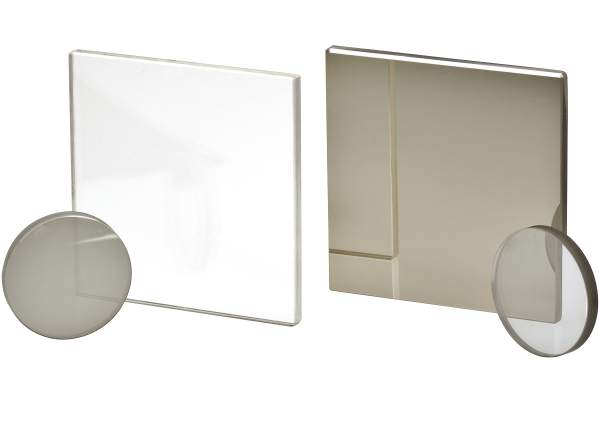
Our metallic neutral density coatings provide broadband attenuation for lower power applications. The precision polished UV fused silica substrate, the filters may be used anywhere from 350 to 2000 nm.
- Broadband attenuation from 350-2000 nm
- Metallic neutral density coating
- Low wavefront distortion
- UV grade fused silica
- For lower power applications
- Available in convenient kits See All Features
| Compare | Description | Drawings, CAD & Specs | Avail. | Price | ||
|---|---|---|---|---|---|---|
 | FRQ-ND003 | In Stock FREE 2-day shipping on thousands of products on Newport.com Learn More | ||||
 | FRQ-ND01 | In Stock FREE 2-day shipping on thousands of products on Newport.com Learn More | ||||
 | FRQ-ND02 | In Stock FREE 2-day shipping on thousands of products on Newport.com Learn More | ||||
 | FRQ-ND03 | In Stock FREE 2-day shipping on thousands of products on Newport.com Learn More | ||||
| FRQ-ND04 | In Stock FREE 2-day shipping on thousands of products on Newport.com Learn More | ||||
 | FRQ-ND05 | In Stock FREE 2-day shipping on thousands of products on Newport.com Learn More | ||||
 | FRQ-ND06 | 6 Weeks FREE 2-day shipping on thousands of products on Newport.com Learn More | ||||
| FRQ-ND07 | 5 Weeks FREE 2-day shipping on thousands of products on Newport.com Learn More | ||||
 | FRQ-ND08 | In Stock | ||||
| FRQ-ND09 | |||||
| FRQ-ND10 | 4 Weeks FREE 2-day shipping on thousands of products on Newport.com Learn More | ||||
| FRQ-ND15 | In Stock FREE 2-day shipping on thousands of products on Newport.com Learn More | ||||
 | FRQ-ND20 | In Stock FREE 2-day shipping on thousands of products on Newport.com Learn More | ||||
 | FRQ-ND25 | In Stock FREE 2-day shipping on thousands of products on Newport.com Learn More | ||||
 | FRQ-ND30 | In Stock FREE 2-day shipping on thousands of products on Newport.com Learn More | ||||
 | FRQ-ND40 | In Stock FREE 2-day shipping on thousands of products on Newport.com Learn More | ||||
 | FSQ-ND003 | In Stock FREE 2-day shipping on thousands of products on Newport.com Learn More | ||||
 | FSQ-ND01 | In Stock FREE 2-day shipping on thousands of products on Newport.com Learn More | ||||
 | FSQ-ND02 | In Stock FREE 2-day shipping on thousands of products on Newport.com Learn More | ||||
 | FSQ-ND03 | In Stock FREE 2-day shipping on thousands of products on Newport.com Learn More | ||||
 | FSQ-ND04 | In Stock FREE 2-day shipping on thousands of products on Newport.com Learn More | ||||
 | FSQ-ND05 | In Stock FREE 2-day shipping on thousands of products on Newport.com Learn More | ||||
 | FSQ-ND06 | In Stock | ||||
 | FSQ-ND07 | In Stock FREE 2-day shipping on thousands of products on Newport.com Learn More | ||||
 | FSQ-ND08 | In Stock FREE 2-day shipping on thousands of products on Newport.com Learn More | ||||
 | FSQ-ND09 | |||||
 | FSQ-ND10 | 3 Weeks FREE 2-day shipping on thousands of products on Newport.com Learn More | ||||
 | FSQ-ND15 | 3 Weeks FREE 2-day shipping on thousands of products on Newport.com Learn More | ||||
| FSQ-ND20 | In Stock FREE 2-day shipping on thousands of products on Newport.com Learn More | ||||
| FSQ-ND25 | In Stock FREE 2-day shipping on thousands of products on Newport.com Learn More | ||||
| FSQ-ND30 | In Stock FREE 2-day shipping on thousands of products on Newport.com Learn More | ||||
| FSQ-ND40 | In Stock FREE 2-day shipping on thousands of products on Newport.com Learn More |

Specifications
- Wavelength Range350 - 2000 nm
- Angle of Incidence0°
- MaterialUV grade fused silica or equivalent
- Damage Threshold30 W/cm2 CW, typical; not recommended for pulsed laser use
- Thickness3.0 mm
- Thickness Tolerance±0.25 mm
- Surface Quality60-40 scratch-dig
- Clear Aperture≥central 80% of dimensions
- Wedge≤3 arc min
- Chamfers0.25–0.76 mm face width
- Chamfers Angle Tolerance45° ±15°
- DurabilityMIL-C-48497A, adhesion, humidity, moderate abrasion, and solubility requirements
- Cleaning
Features
Finely Control Beam Attenuation
Metallic Coating Properties
Due to the absorptive nature of the metallic coating, use with high-power lasers should be avoided. Power levels less than 30 W/cm2 are advised.
For additional attenuators, see Laser Beam Attenuators
Additive Optical Densities
UV Fused Silica Substrate
Proper Orientation
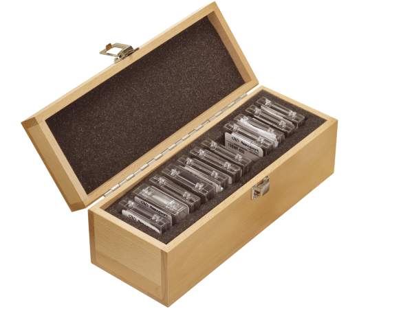
Neutral Density Filter Kits
The FR-ND UV Fused Silica Metallic Neutral Density Filter Set includes eight, 25.4 mm diameter, UV Fused Silica Metallic ND Filters. The FS-ND UV Fused Silica Metallic Neutral Density Filter Set includes eight, 50.8 x 50.8 mm square, UV Fused Silica Metallic ND Filters. Each kit includes optical densities of 0.03, 0.1, 0.3, 0.5, 1.0, 2.0 and 3.0. Our metallic neutral density coatings provide broadband attenuation for lower power applications. The coating is deposited on one side of an ultra-pure UV grade fused silica substrate providing excellent transmission from the UV to NIR. Filter kits provide convenience and cost savings.